66 Rockwell Automation Publication 442L-UM005B-EN-P - April 2017
Chapter 6 Application Examples and Connection Diagrams
Mobile Applications
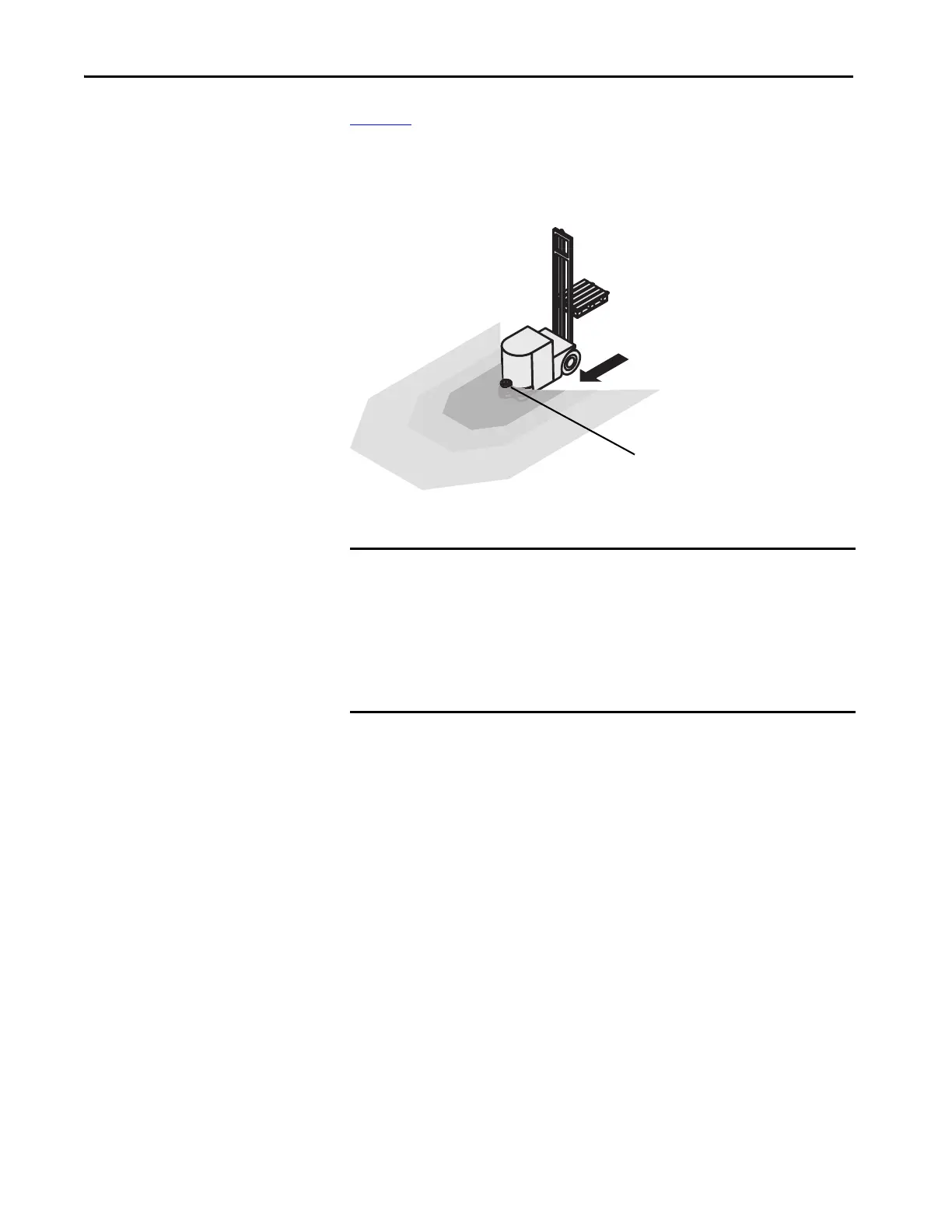
Figure 42 shows vehicle monitoring for unidirectional travel with a SafeZone
Mini device. The SafeZone Mini device monitors the area in the direction of
travel and switches its OSSDs to the OFF state to stop the vehicle as soon as
there is an object in the protective field.
Figure 42 - Vehicle Monitoring
Connection Diagrams
SafeZone Mini with one protective
field and two warning fields
IMPORTANT • Only use relays/contacts with positively guided contacts. The protection
elements connected in parallel with the relays/contactors are used for
arc-suppression.
• Verify that there is adequate arc-suppression at the relays/contactors.
Consider that arc-suppressors can lengthen the response time.
• The arc-suppressors must be in parallel with the relays/contactors (not
across the contacts).
 Loading...