Addressing Reference
SLC 500 Family of Programmable Controllers
13
The recommended default file for floating-point elements is file 8 of the
data table. This file accommodates up to 256 floating-point elements. If
your application requires more than 256 floating-point elements, specify
one or more files (10 – 255) in the user-defined area of the data table in
addition to file 8.
Each floating-point element consists of two words. You must address the
floating-point element in its entirety.
Figure 13
Logical
Addressing for Floating-Point Elements
File Type
F = Floating-Point
Element Number
0 – 255 decimal
Logical Address Identifier
File Separator
$ F 8 : 123
File Number
8 or
10 – 255
decimal
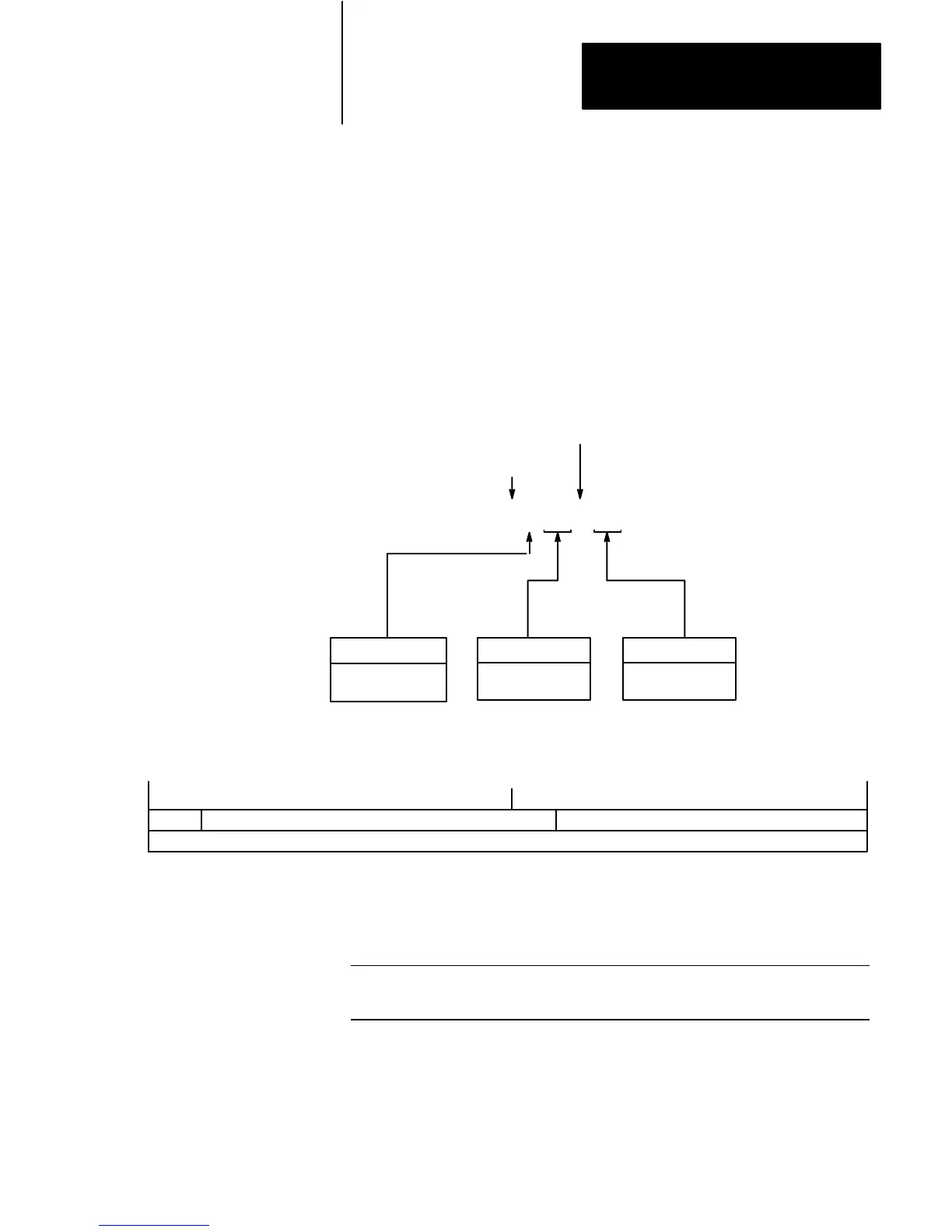
Figure 14
Bit Map of the Floating-Point Element
1514131211109876543 2 10
S MANTISSA (23-bits)EXPONENT (8-bits)
MANTISSA (cont)
Word 0
Word 1
T
able J
Parameters
of Floating-Point Elements
Description PLC Data Type Valid Range
Floating-Point Element
IEEE Float $1.1754944 E–38
thru
$028237 E+38
Logical Addressing for
Floating-Point Elements

 Loading...


