Addressing Reference
SLC 500 Family of Programmable Controllers
3
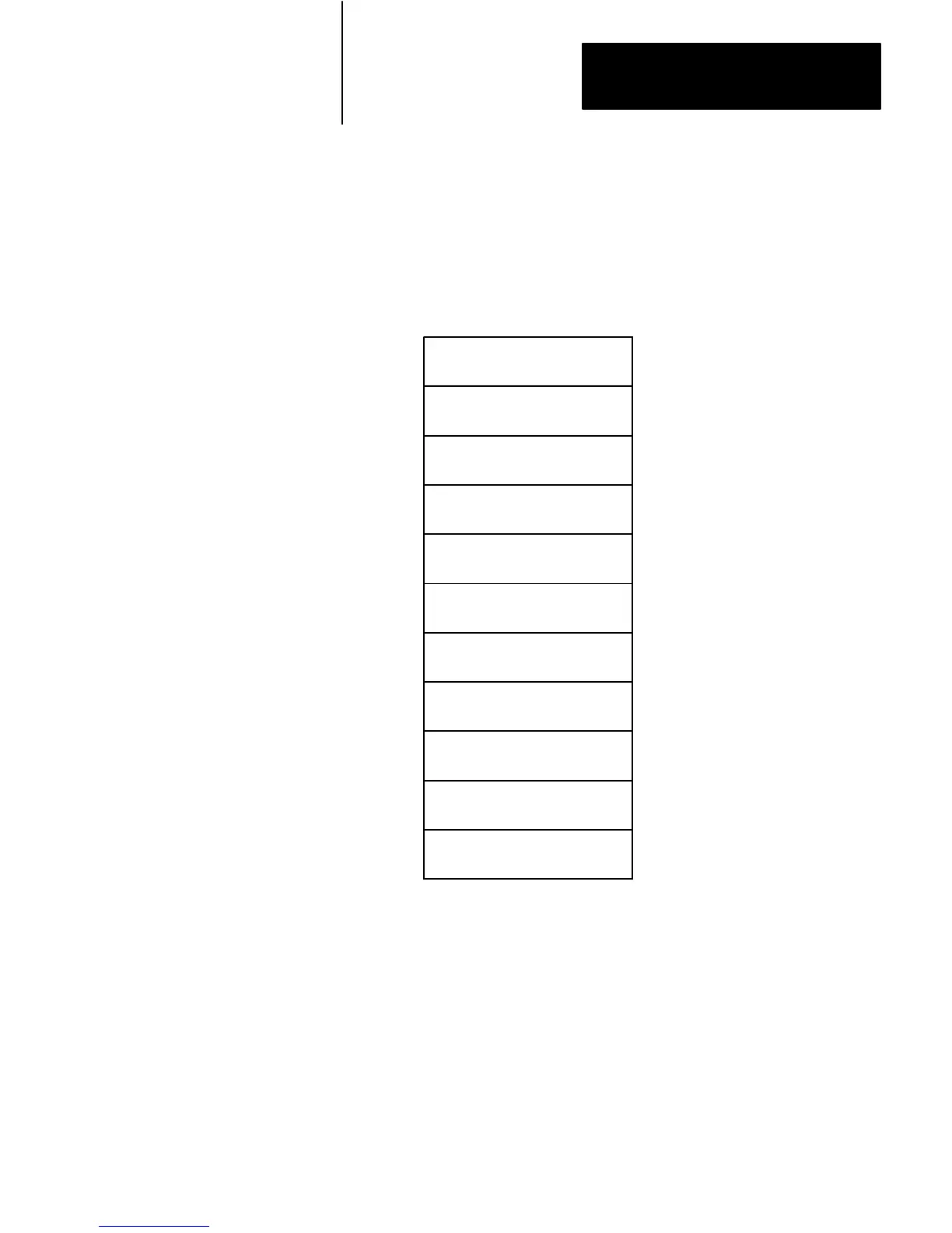
Table A shows the logical arrangement of the data table for SLC 500
processors.
T
able
A
Data
T
able Memory Map
OUTPUT IMAGE
INPUT IMAGE
STATUS
BINARY
TIMER
COUNTER
CONTROL
INTEGER
FLOATING–POINT
$O:0
$O:30
$I:0
$I:30
$S:0
$S:n
$B3:0
$B3:255
$T4:0
$T4:255
$C5:0
$C5:255
$R6:0
$R6:255
$N7:0
$N7:255
$F8:0
$F8:255
$x10:0
$x255:255
NETWORK
USER DEFINED
File
Number
File
Type
Logical
Address Comments
$x9:0
$x9:255
See Note 1
See Note 2
See Note 3
See Note 4
0
1
2
3
4
5
6
7
8
9
10
thru
255
to
to
to
to
to
to
to
to
to
to
to
Notes
1 Address range is processor specific; see Logical Addressing for the Status Elements section.
2 Only the SLC 5/03 series B processor supports floating-point data type. Do not use this area for
processors that do not support floating-point data.
3 If non SLC 500 devices exist on the DH-485 link, use this area for network transfer. You can use
either binary (B) or integer (N) file types by specifying the appropriate letter for x. Otherwise, you can
use file 9 for user-defined files.
4 Use this area when you need more binary, timer, counter, control, integer, floating-point, or network
files that will fit in the reserved files. You can use binary (B), timer (T), counter (C), control (R), integer
(N), floating-point (F), or transfers (B and/or N) file types by specifying the appropriate letter for
x
. You
cannot use this area for output image, input image, and/or status files.
Memory
Map

 Loading...


