Addressing Reference
SLC 500 Family of Programmable Controllers
15
The recommended default file for timer structures is file 4 of the data table.
This file accommodates up to 256 timer structures. If your application
requires more than 256 timer structures, specify one or more files (10 –
255) in the user-defined area of the data table in addition to file 4.
Each timer structure consists of three words. You can address a timer
structure in its entirety or you can address any particular member of a
structure individually.
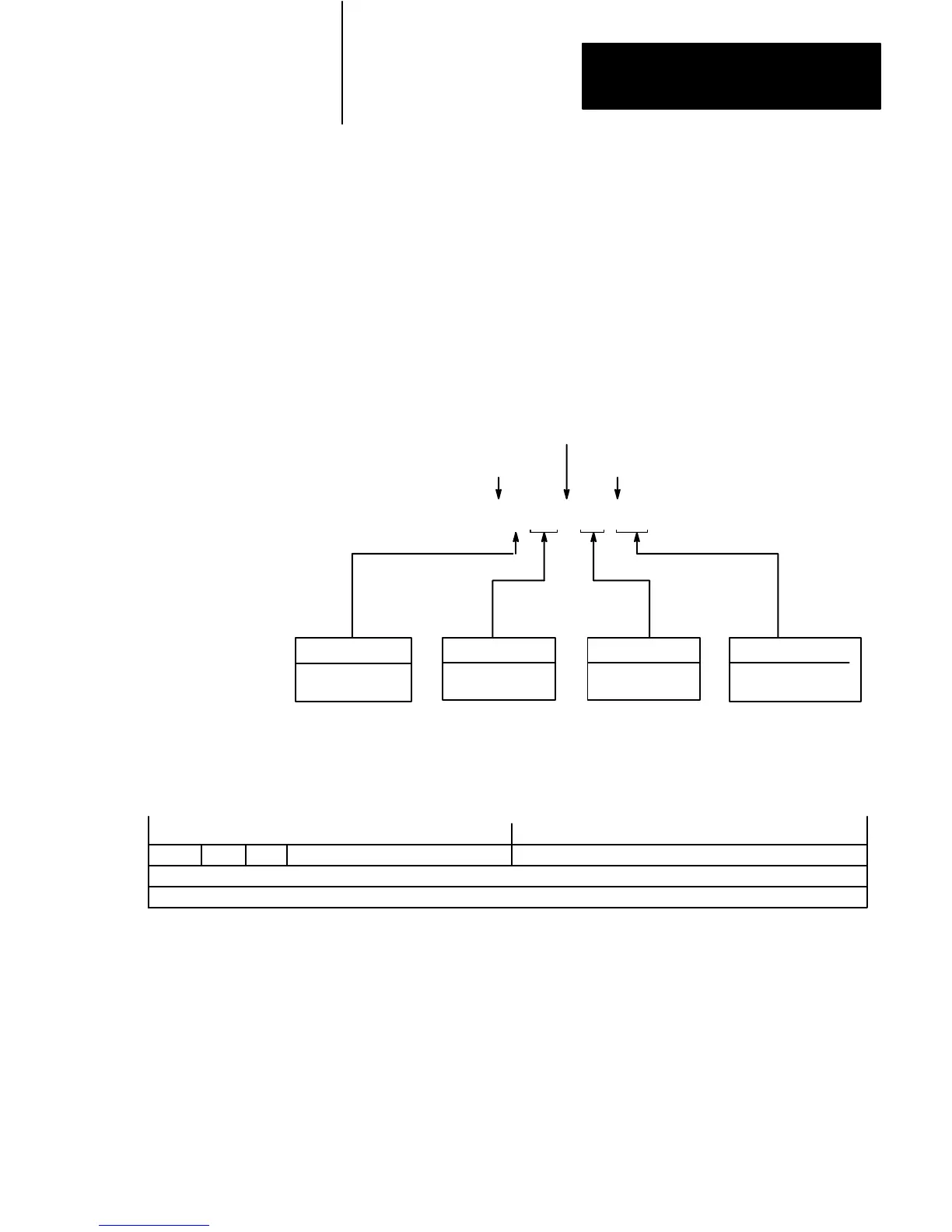
Figure 15
Logical
Addressing for T
imer Structures
File Type
T = Timer
Member Mnemonic*
See Table L
Structure Number
0 – 255 decimal
Logical Address Identifier
File Separator
Member Mnemonic Separator*
$ T 4 : 123 .ACC
File Number
4 or
10 – 255 decimal
*Required only if addressing to the member level.
Figure 16
Bit Map of the T
imer Structure
1514131211109876543 2 10
EN RESERVEDRESERVED
PRE
Word 0
Word 1
Word 2
ACC
TT DN
Logical Addressing for
Timer Structures

 Loading...


