Addressing Reference
SLC 500 Family of Programmable Controllers
4
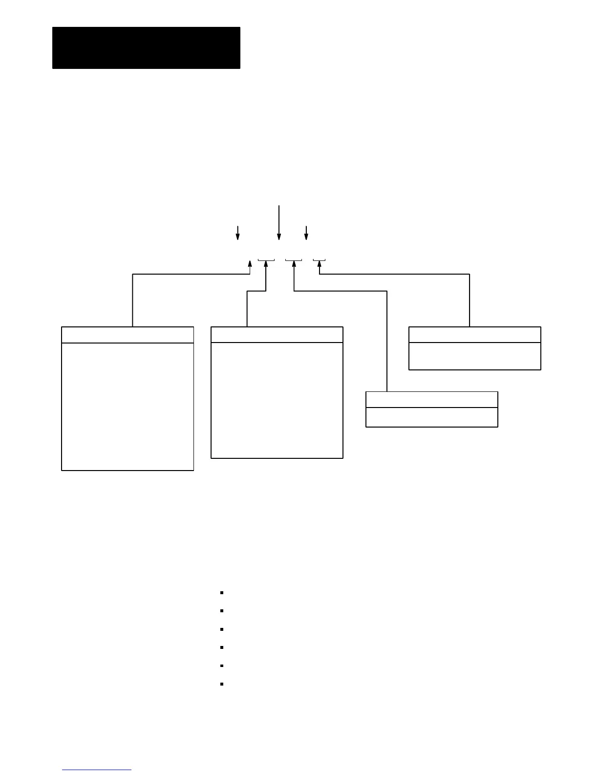
Figure 1 illustrates the general format for logical addressing in the data
table.
Figure 1
General
Format for Logical Addressing
File Type
A = ASCII
B = Binary
C = Counter
D = Decimal (BCD)
F = Floating-point
2
I = Input
N = Integer
O = Output
R = Control Block
S = Status
ST = ASCII String
2
T = Timer
File Number
0 = Output
1 = Input
2 = Status
3 = Binary
4 = Timer
5 = Counter
6 = Control Block
7 = Integer
8 = Floating-point
10-255 = User-defined
Bit Number
0 – 15 decimal
Element or Structure Number
0 – 255 for all files except Status
1
Logical Address Identifier
File Separator
Bit Separator (if addressing a bit)
$ B 123 : 123 / 15
Notes:
1
The number of elements (words) in the status file is processor dependent;
see Logical Addressing for the Status Element section.
2
ASCII string, floating-point, and network file types are not available on
SLC 500, SLC 5/01, SLC 5/02, SLC 5/03 processors.
You can address individual bits for the following elements in a data table
file by absolute bit number (0 thru 4095):
binary
control block
input image
integer
output image
status
General Format for Logical
ASCII Addressing

 Loading...


