508433-01Issue 2345Page 20 of 70
Switch 5 -- Cooling Mode Blower-O Delay -- The unit
is shipped from the factory with the dip switch positioned
OFF for a 45 second delay. Table 6 provides the cooling
mode o delay settings.
Blower O Delay
(seconds)
Switch 5
45 (Factory) O
2 On
Table 6. Blower O Cooling Mode Delay Switch
Settings
Switches 6 and 7 -- Continuous Fan Mode -- Continuous
fan speed can be controlled by changing DIP switch
positions. Table 7 provides DIP switch settings for
continuous fan mode.
Continuous Fan
Mode
Switch 6 Switch 7
Low Heat Speed
(Factory)
O O
Low Cool Speed O On
High Heat Speed On O
High Cool Speed On On
Table 7. Continuous Fan Mode Settings
Onboard Links
W914 Dehum
Onboard link W914, is a clippable connection between
terminals R and DS on the integrated control. W914 must
be cut when the furnace is installed with a thermostat which
features humidity control. If the link is not cut, terminal “DS”
will remain energized not allowing the blower to reduce to
low cool speed upon a call for dehumidication.
W951 Heat Pump (R to O)
Onboard link W951 is a clippable connection between
terminals R and O on the integrated control. W951 must
be cut when the furnace is installed in applications which
include a heat pump unit and a thermostat which features
dual fuel use. If the link is left intact, terminal “O” will remain
energized eliminating the HEAT MODE in the heat pump.
W915 2 Stage Compr (Y1 to Y2)
Onboard link W915 is a clippable connection between
terminals Y1 and Y2 on the integrated control. W915 must
be cut if two-stage cooling will be used. If the Y1 to Y2
link is not cut the outdoor unit will operate in second-stage
cooling only.
If any onboard link is cut by mistake, install a jumper
across the corresponding terminals on the low voltage
terminal strip. Do not replace control.
IMPORTANT
Blower Compartment
Each blower is statically and dynamically balanced as
an assembly before installation in the unit.
IMPORTANT
A97UH2E units are equipped with a constant torque ECM
motor. It has a DC motor coupled to an electronic control
module both contained in the same motor housing. The
motor is programmed to provide constant torque at each of
the ve selectable speed taps. Each tap requires 24 volts
to energize.
Input Voltage Requirements
The circuit is designed to be operated with AC voltage. To
enable a tap requires 12 to 33VAC. Expected current draw
will be less than 20mA.
Troubleshooting the Motor
Troubleshooting the motor is an easy process. Follow
steps below.
1. Shut o power to unit.
2. Remove input plugs P48 and P49 from motor. See
Figure 10 for troubleshooting procedure.
If correct voltage is present in tests 1 and 2 and motor is
not operating properly, replace motor. The motor is not eld
repairable.
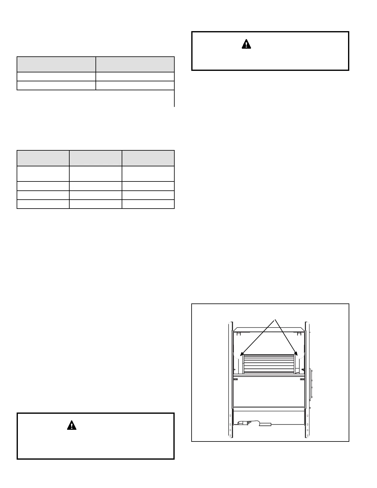
If replacing the indoor blower motor or blower wheel is
necessary, placement is critical. The blower wheel must
be centered in the blower housing as shown in Figure 6.
When replacing the indoor blower motor the set screw
must be aligned and tightened with the motor shaft as
shown in Figure 7.
Figure 6. Blower Wheel Replacement
Center Blower Wheel
in Blower Housing