T4PGF1 INSTRUCTION MANUAL Page 6
SHAW-ALMEX INDUSTRIES LIMITED June 14 2017
5. ASSEMBLY
5.1. Unpacking
Carefully unpack temperature control panel from the crate and inspect for damage.
Any damages or shortages should be reported to the carrier and / or Shaw-Almex Industries Limited.
5.2. Functional Diagram
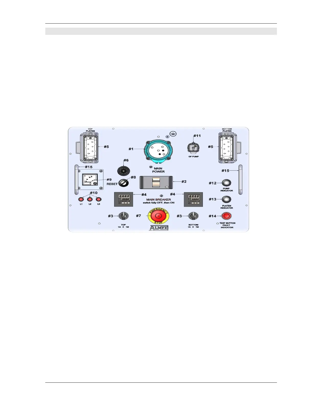
T4PGF1 – Face Component Locations
1. Power Supply Connector (1REC) 2. Main Breaker (1CB)
3. Platen Switch (x2) (24-30SS) 4. Platen Temperature Control (x2) (18-25TC)
5. Platen Connector (x2) (5-11REC) 6. Alarm - over temperature audible (73ABU)
7. Emergency Stop Switch (23PB) 8. Keyed Reset / Start Switch (18PB)
9. Ammeter (AM1) 10. Phase Indicator Lights (PL1-3)
11. Pump Plug (39REC 12. Pump Earth Indication Light (PL80)
13. Platen Earth Indicator Light (PL79) 14. Earth Fault Test and Indication Light (47PB)
15. Face Plate Removal Handles (HN) 16. Face Mounting Screws, ( not shown )
See Page 22 For Parts List And Descriptions