T4PGF1 INSTRUCTION MANUAL Page 7
SHAW-ALMEX INDUSTRIES LIMITED June 14 2017
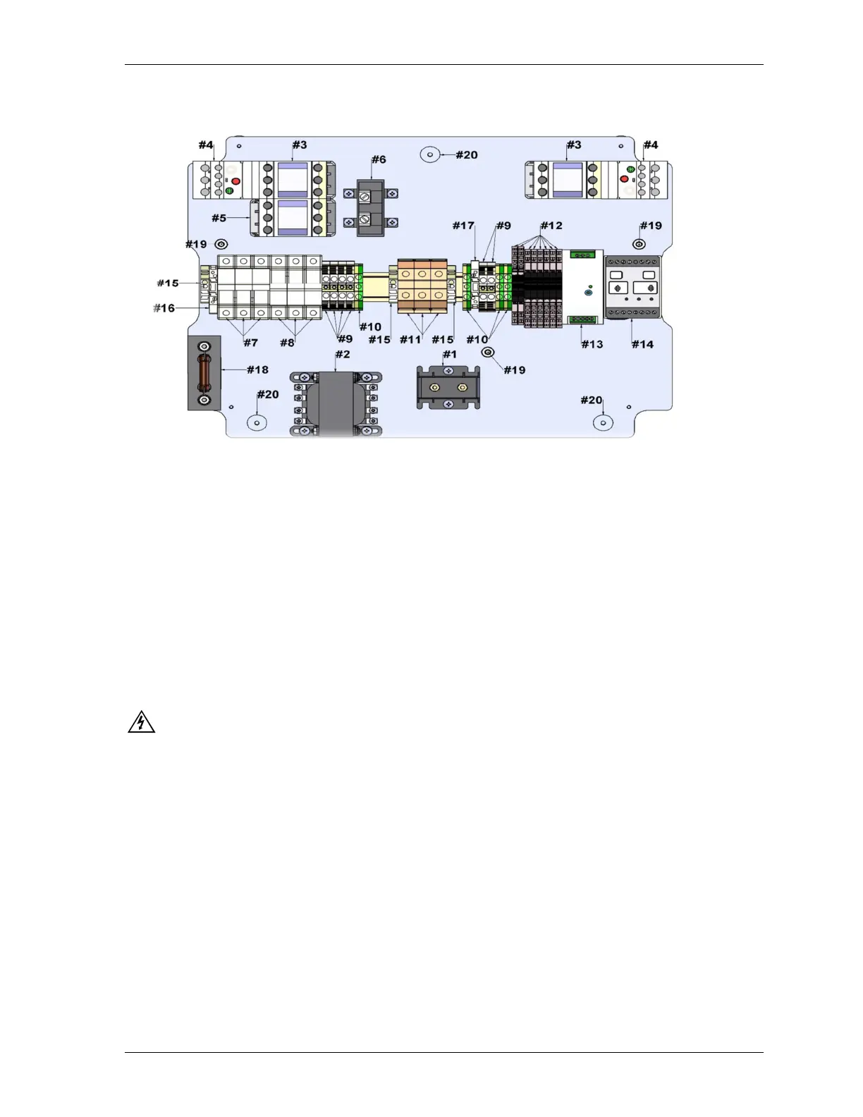
T4PGF1 – Internal Component Locations
1.
Earth fault Current Transformer (9CT) 2. Control Power Transformer (12T)
3. Platen Contactors (22-39CON) 4. Platen Thermal Overloads (22-39CON)
5. Pump Contactor (22-39CON 6. Load Current Transformer (1AM)
7. Power Transformer and Phase Light Fuses (9FU) 8. Pump Fuses (39FU)
9. Terminal Blocks (*STER) 10. Ground/Earth Terminals (*GTER)
11. High Voltage Terminal Blocks (*TER) 12. Detecting Relays and Resistors (R85-104)
13. Power Transformer 120 to 12v DC (80PS) 14. Earth Leakage Detector Relay (47MON)
15. Terminal Locks (*LCK) 16. Transformer Output Fuse (15-82FU)
17. 12 DC Transformer Output Fuse (15-82FU) 18. Earth Leakage Fault Resistor and Base (9R)
19. Ground/Earth Lugs 20. Base to Face Aluminum Standoffs (*ST)
See Page 22 For Parts List And Descriptions.
5.3. Connection Assembly
SAFETY- Ensure the voltage, phase and cycle on the temperature control panel is the same as the power
supply.
Turn the top and bottom platen switches to the 0 (off) position.
1. Install a suitable electrical connector to the power supply cable. Refer to the electrical specifications
indicated on the serial plate and in the record of purchase. Connect the GREEN and SILVER wire to earth.
2. Connect the power supply cable to the power supply receptacle on the center face of the temperature
control panel. This is an Arc Flash and Switch rated type of connector that is used for ground fault
protected Almex control systems.
3. The platen connectors are on the face of the temperature control panel. Connect the platen cables by
pressing the plugs firmly into the receptacles and rotate the latches to secure the plugs. Please note: GF
platen and cable male plugs will have pin #6 shorter than the rest. This allows the pilot circuit to break first
removing the power eliminating arc flash, power to disconnect second and earth or ground to disconnect
last.
4. Connect the temperature control panel to the power supply. The phase indication lights will show that
power is supplied to the lines lit. If all line Indicators do not illuminate, have a qualified person check the
problem.