-F10 -F11
L Y2
A1
A2
4
1
5
2
P
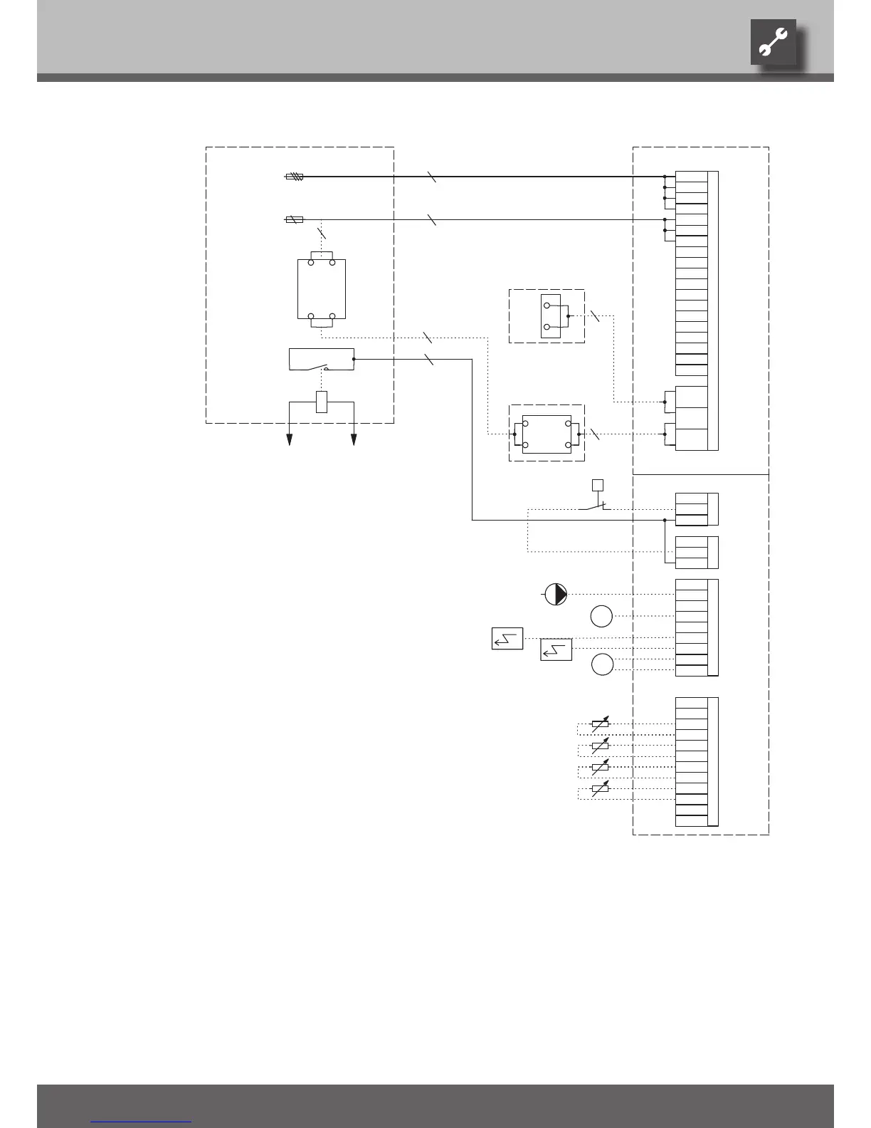
Brine water compact 23 - 33 kW
L1
N
3
230V
ASD
-X2
TBW
A3
L1
BUP
TB1
GND
MZ1
2
N
-X0
TA
PE
L1
2
N
MA1
2
ZW2/SST
A2
FP1
N
TBW
EVU
N
1
PE
RFV
-T2
2
L1
4
L1
2
-X4-X3
EVU
MOT
PE
2
PE
ASD
VBO
A1
TA
-Y3
PE
GND
TRL
ZW1
24V
TB1
L3
MIS
PEX
ZW2/SST
M
GND
L2
HUP
GND
3
B10 A
BUP
ZW1
PE
-Y2
M
FP1
23kW: C16 A
33kW: C25 A33kW: C25 A
Terminal strip in switchbox of heat pump; N/PE distribution for external 230V units
Control signal of additional heat generator 1
X7:PE,N,L1
3~PE/400V/50Hz
Control signal of additional heat generator 2 (alternative is general malfunction)
Power supply compressor 3 x 400V; Attention: Right-hand rot. field is mandatory!
Control 230V
X0-X4
ZUP/ZIP
Terminal strips on controller board (see sticker)
Charge/discharge/cooling mixer 1 closed
Auxiliary circulation pump / circulation pump
Accessories: Remote control
TA
ZW2/SST
X7
Brine circulation pump
ZW1
X7:PE,L1,L2,L3
TBW
HUP
Name
A1
Heating circuit circulation pump; internally wired
ASD
23 - 33 kW
Accessories: Process water sensor/thermostat
Brine pressure pressostat; provided by cust. if necessary
A2
Y2
VBO
Terminals
A3
F11
Accessories: Process water for changeover valve
T2
Sub-distribution unit internal installation
TB1
Charge/discharge/cooling mixer 1 open
-X7
Cut out controller unit
Accessories with cooling option: Dewpoint monitor; bridge if not connected
Energy supplier contact; closed on release; bridge if no blocking interval
UK831122a
Accessories: Transformer for dewpoint monitor
With cooling option: Room thermostat; bridge if not connected
N
Legend:
F10
GND
GND
1~N/PE/230V/50Hz
RFV
N
PE
PE
BUP
ZUP/ZIP
MZ1/MIS
no function
TRL
MA1/MIS
Overload protection; internally wired
PEX
Controller board; Attention: I-max = 6A/230VAC
FP1
MOT
External sensor
Y3
Terminals in heat pump switchbox
Pump for mixing circuit 1
Function
3-pol. Cut out compressor; Attention: Right-hand rot. field is mandatory!
Sensor mixing circuit 1
External return sensor
EVU
RFV
1 2 3 4 5 6 7 8 9 10 11 12 13 14 15 16
1
20.02.2007
1 2 3 4 5 6 7 8 9 10 11 12 13 14 15 16
08.12.2006Georg Bächmann
Georg Bächmann
SWC 230-330 terminal diagram
831122a
1/1
Ers. für
Anlage
Ort
Ers. durch
Name
Datum
Urspr.
Blatt-Nr.
Bl von AnzNorm
Zustand
Bearb.
Gepr.
Änderung Datum

 Loading...