The following example uses this configuration:
i) Controller is set up to use a thermistor type sensor (10Kohms @ 25°C) on the 0 to 100K
range (
[`)00] to [9(99]) by following the instruction in Section 4.0 under “Sensor
Programming & Configuration”
ii) The controller being used is a 150 Watt which has a +15V power supply and a Maximum
Current specified at 10 Amperes.
Knowing the controller’s set up information above will allow one to quickly determine
what the controller is doing at any given time by simply analyzing the front panel while
at the Home Page
1
.
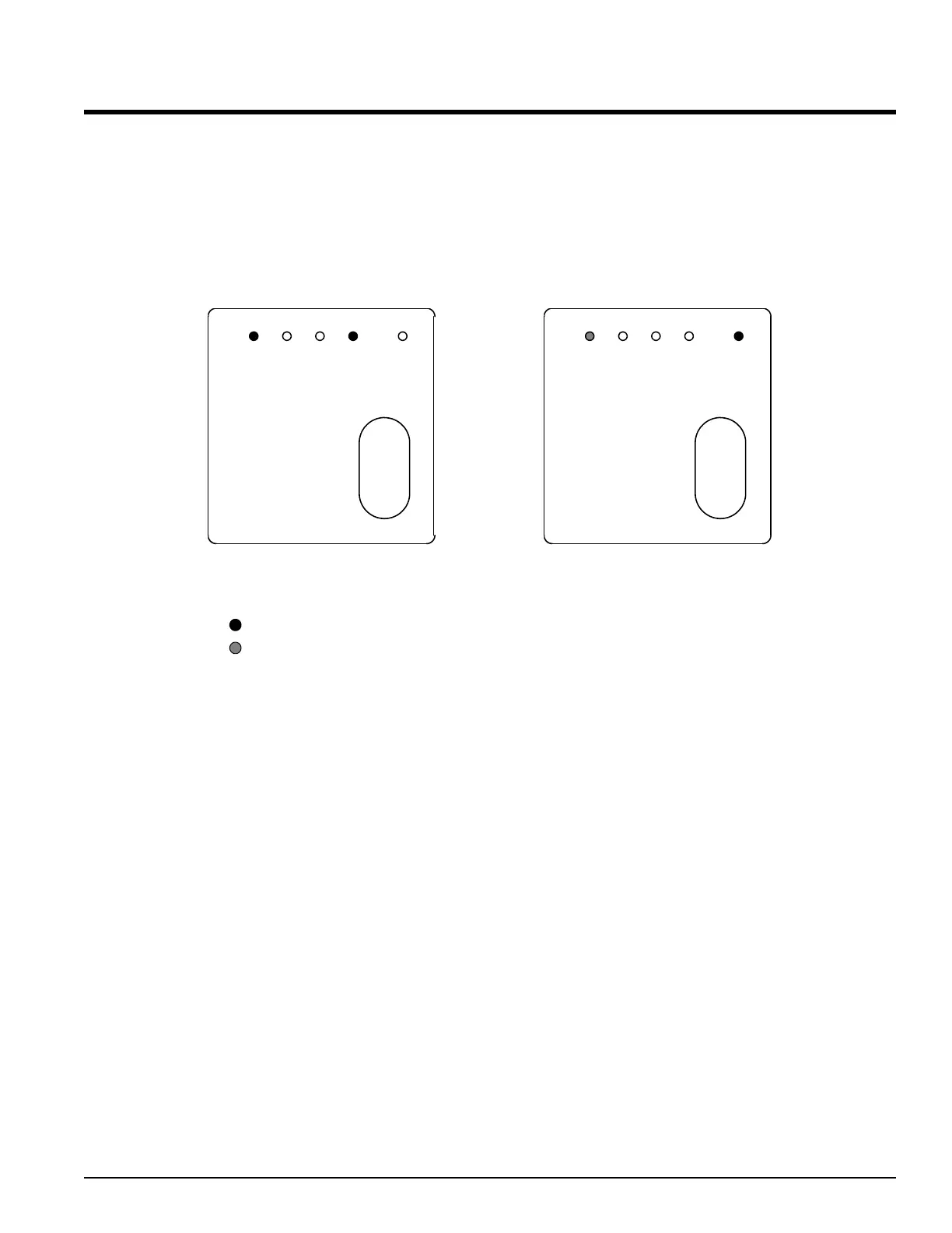
Above are two front panel drawings. Examining the drawing on the left, one can
quickly see that Output 1 is on because the light is on. The Output 1 light always
corresponds to Cooling, therefore the controller should be outputting positive current to
the thermoelectric cooler (TEC).
The drawing on the right indicates that the controller is in manual mode since the %
light is ON. Notice how the lower display is at -50%. This indicates the power level
and the polarity. The reason for this is that thermistors are negative temperature
coefficient devices and the negative sign would indicate “Cooling” while a positive
number would indicate “Heating”. All positive temperature coefficient devices will
indicate a positive % output for “Cooling” and a negative % output for “Heating”.
ALPHA OMEGA INSTRUMENTS CORP. Instruction Manual
Series 800/850 Thermoelectric Cooler Controller Page 66
¿
[3)59]
[4%00}
1234
Home
‰¯ˆ
%
¿
[2@87]
[-5)0}
1234
Home
‰¯ˆ
%
ON STEADY = 100% CURRENT
50% DUTY CYCLE = 50% CURRENT
LIGHT'S DUTY CYCLE = PERCENT CURRENT OUTPUT
LEGEND:
1
To get to the Home Page at any time simply press the infinity key (ˆ).
 Loading...