Appendix B
POWER BOOSTER MODULE
A Power Booster Module (PBM) is simply a power supply housed in the same form
factor as the Main controller. The only difference is that the Main controller has a front
panel with controls and optional I/O capabilities. The PBM only has a power supply
and a single I/O channel for either being conrtrolled by a Main controller or controlling
another PBM.
Wiring
On the rear of both the main controller and the PBM are two connectors labeled
“CTRL”.
1
One of the connectors is labeled “IN” and the other is labeled “OUT”. Simply
connect the main controllers “CTRL OUT” connector to the PBM’s “CTRL IN”
connector using the supplied RJ-11 6 conductor cable.
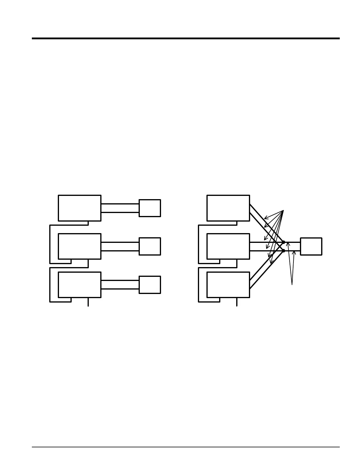
Below shows how to connect multiple PBM’s to a main controller.
Main
Controller
PBM
PBM
IN OUT
IN OUT
IN OUT
To other PBM's
TEC
TEC
TEC
Main
Controller
PBM
PBM
IN OUT
IN OUT
IN OUT
To other PBM's
TEC
#14 wire for 10 Amps
#12 wire for 30 Amps
The combination of the outputs from the main controller and any number of PBM’s can
be connected to separate TECs or a single TEC. Keep in mind that the outputs must
be in PARALLEL and never in series when driving a single TEC. The maximum
current per connector pin is 10 amperes.
Be sure to use heavy guage wire if paralleling outputs to a single TEC. The wire size
should be appropriate for how much current is flowing and the length of the conductor.
ALPHA OMEGA INSTRUMENTS CORP. Instruction Manual
Series 800/850 Thermoelectric Cooler Controller Page 59
1
Note: At this time, the main controller’s “CTRL IN” connector is for future enhancements and should not be used.
 Loading...