SYSTEM CONFIGURATION
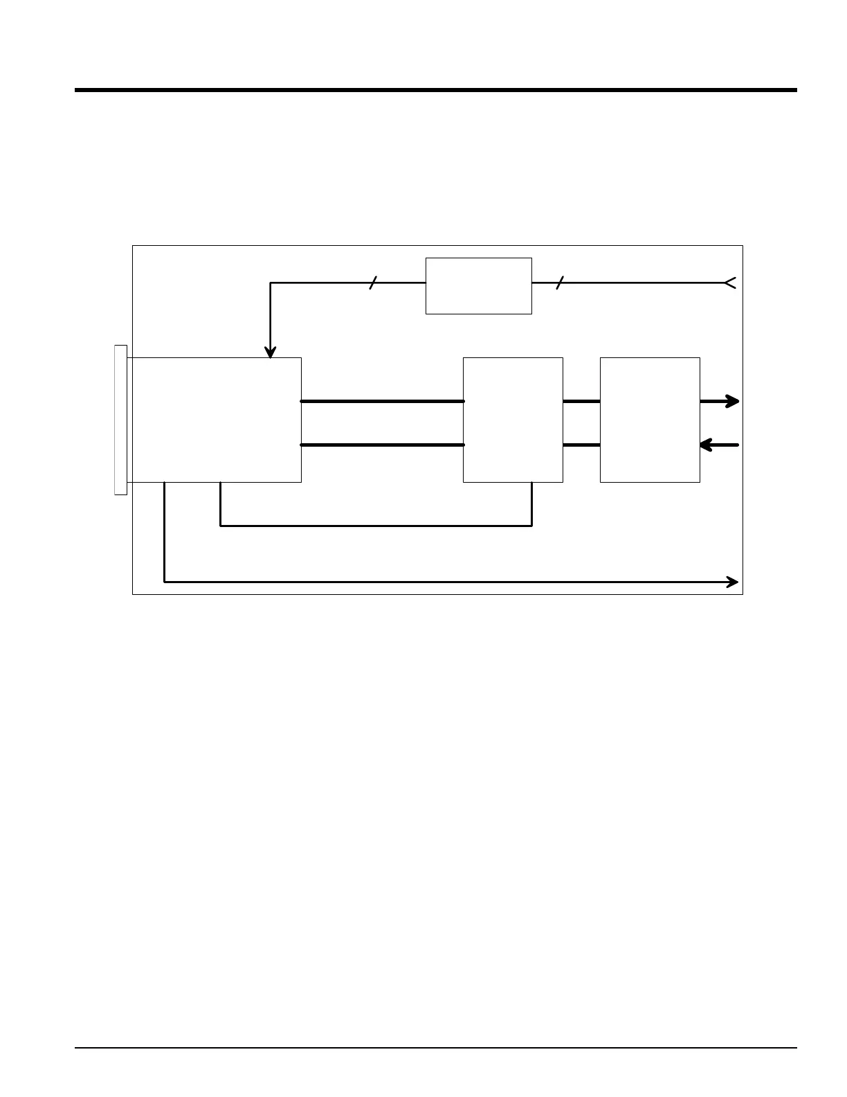
The diagram below shows the basic inputs and outputs of the Series 800/850
thermoelectric cooler controller.
Out 1
Out 2
Out 3Out 4
Input 1
Sensor
Scaling
Power
Control
Power
Switch
+
Heat
Cool
3 3
Temperature Limit Alarms (Shutdown)
Optional RS232 / RS485 / or Analog output
[Pb`1] [It`1] [De`1]
[Pb`2] [It`2] [De`2]
Input 1 allows for many different types of sensors and each sensor has it’s own
specified temperature range. When looking at the rear of the instrument you will
notice a 3 pin connector on the rear panel. This is the Sensor Input Connector. The
color of this connector will tell you what type(s) of temperature sensor the Series
800/850 TEC Controller is configured for. Please refer to the table on the next page
for details on the sensor types associated with the different colored Sensor Input
connectors. The wiring of the sensors is covered in Section 1.0
Appendix A
ALPHA OMEGA INSTRUMENTS CORP. Instruction Manual
Series 800/850 Thermoelectric Cooler Controller Page 55
 Loading...