ALPINE MRV-M1200 68-29530Z91-A (EN/FR/ES)
11-EN
EN
FR
ES
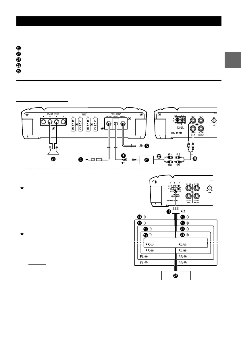
SYSTEM DIAGRAMS
When you connect one or multiple subwoofers, please take care to configure the correct total impedance
before connecting to subwoofer(s) to the amplifier.
Subwoofer
Head Unit, etc.
Subwoofer Output
RCA Extension Cable (Sold Separately)
Y-Adapter (Sold Separately)
TYPICAL SYSTEM CONNECTIONS
1 Subwoofer System
White Violet/Black
Gray/Black Green
Green/Black
Violet
Violet/Black
White/Black Violet
Gray
Gray Green/Black
White/Black
Gray/Black Green
White
Connecting to the Speaker Level Input System
1 For the “Speaker Level Input System” setting,
connecting the Remote Turn-On Lead is not
required due to the “REMOTE SENSING” function of
this product. However, the “REMOTE SENSING”
function may not work depending on the signal
source connected. In such a case, connect the
Remote Turn-On Lead to an incoming power
supply cord (accessory power) in the ACC position.
2 If connecting both Speaker Input Leads and RCA
Inputs at the same time, do not connect both
signals to the same input channel of the amplifier.
Instead, be sure to connect each pair of inputs to a
different Input channel pair.
example;
Speaker Input Leads:
FL/FR to CH1/CH2, RL/RR to CH3/CH4
RCA Inputs:
SUBWL/SUBWR to SUBWL/SUBWR
to a
e cause.
dicator
lt your
to a