HYC200 – Installation and Maintenance Manual
Version 1-1
6 Mechanical and electrical installation
All rights reserved. Reproduction of this document, even in part, is only permitted with the approval of Alpitronic Srl.
6.7. Attaching the grid cables
After the Hypercharger has been mechanically installed, the power lines can be connected
to the busbars of the input switchgear.
Notice
The screws (M12 x 30 and M12 x 85) on the input rails are already
present.
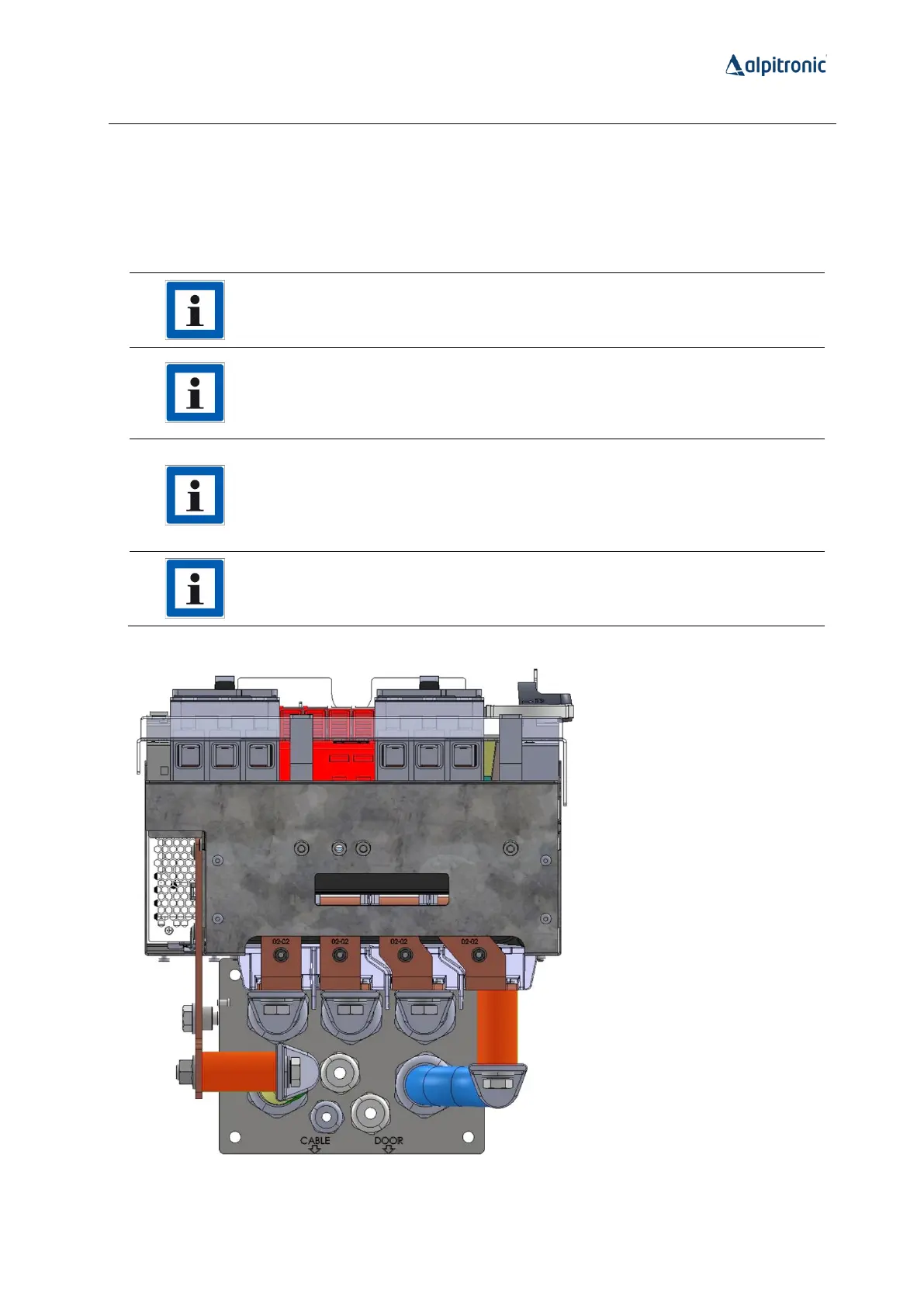
Due to the limited installation space, the grid cables are mounted offset
on the busbars of the input switchgear. To ensure correct positioning, the
2 brass sleeves supplied must therefore be fitted to the outer cable
connections (see red markings in Figure 55).
In the new version of the cable jig, the offsets of the screw connections
are already modelled (see Figure 52). The brass sleeves therefore do not
need to be attached to the cable jig when preparing the power cables. If
you are still using a cable jig without offsets, the brass sleeves must also
be used when preparing the power cables on the cable jig.
The brass sleeves have a length of 55 mm, an outer diameter of 30 mm
and an inner drilling diameter of 13 mm.
Figure 55: Brass sleeves on the cable jig


 To Next Page