52 • Section 7 — Maintenance
can prevent the blade from lying perfectly at on
its matting surface. Improper cap screw torque or
use of worn or damage cap screws can cause blade
separation. Always make sure proper maintenance
and replacement parts are used.
Notice
When installing new or sharpened blades, discard
the existing mounting cap screws and use new Altec
approved cap screws. Repeated reuse of the cap
screws will decrease their clamping capacity.
Drum Inspection
The cutter drum, air paddles, and blade pockets must
be thoroughly inspected for cracking or deformation. If
cracking or deformation is found please contact Altec
Environmental Products.
Blade Sharpening
Notice
The blades are double edged and have a minimum
usable size of 2” (5.08 cm) measured from the center-
line of the cap screw holes to the blade edge. Do not
use a side of a blade that measures less than this.
• Sharpen blades at a 30 degree angle.
• Use a soft J grade grinding wheel with a 36 to 40
grit.
• Use adequate coolant while grinding.
• Hone blades between sharpening.
Notice
On resharpened blades, measure the distance from
the mounting holes to the sharpened edges. Mount
blades so edges with the same measurements are
oriented the same way at both blade locations.
Anvil Removal/Installation
Danger
Blades and anvils are extremely sharp and can
severely cut your hands. Anytime you are storing,
handling or performing maintenance on blades or
anvils you must wear good quality leather palm
work gloves. This will greatly reduce the possibility
of serious injury.
Falling objects can cause serious eye injury.
Always wear goggles when working overhead.
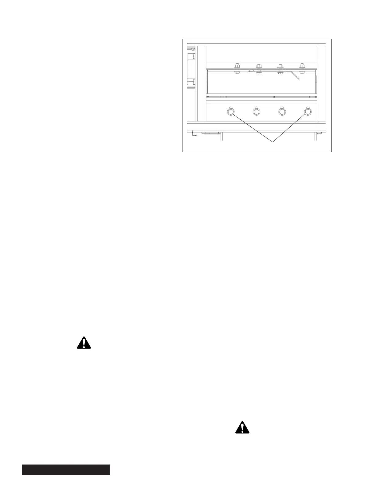
Anvil Removal
1. Remove the four
1
/2-13 cap screws securing the hinged
anvil access cover and anvil/blade gap gauge.
Figure 7.6 — Anvil
2. If needed rotate the drum so cutter blades are not in
the work area.
3. Remove the four
5
/8-11 cap screws.
4. Remove the anvil and thoroughly clean all anvil/drum
head mating surfaces.
Anvil Installation
1. If blades are to be rotated or changed this should be
completed rst. Refer to blade installation.
2. With all areas in the anvil location clean and free of
debris, install the anvil positioned with an unused
cutting edge at the blade to anvil cutting point.
3. Install the four anvil cap screws, do not tighten.
4. Slowly hand rotate the drum. Using the anvil gap
gauge, set the anvil to a blade clearance at the out-
board cap screw to
1
/8”. Hand tighten this outboard
cap screw.
5. Rotate the drum to the other blade, set the outboard
gap and hand tighten the outboard cap screw.
6. While verifying correct gap setting. Slowly hand
rotate the rotor across all anvil/blade contact points
to ensure proper blade/anvil clearance. Adjust as
necessary.
7. Torque anvil cap screws to specications in the
fastener torque table.
Warning
Death or serious injury can occur from blade separa-
tion. Never use an impact wrench to tighten blade
or anvil cap screws. Always use a torque wrench.
Outboard Cap Screws