EasyManua.ls Logo

Altronics CD200 User Manual

Altronics CD200
35 pages
To Next Page IconTo Next Page
Page #1 background imageLoading...
Page #1 background image
ALTRONIC CD200
IGNITION SYSTEM
www.altronicinc.com
FORM CD200 II 5-07
www.altronicinc.com
1
1.0 DESCRIPTION
1.1
This manual provides installation and operating instructions for the
Altronic CD200 ignition system. It is recommended that the user
read this manual in its entirety before commencing operations.
1.2
The Altronic CD200 ignition system consists of these basic components:
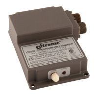
CD200 Unit - 791070-x or 791080-x (see FIG. 1 and FIG. 2)
Magnetic Pickup Sensor (one per system)
Input Harness (one per system)
Output Harness (one or two per system)
Ignition coils (one per cylinder)
1.3
The system requires a battery or a suitable power supply
with a nominal 12 Vdc or 24 Vdc (see FIG. 3). The CD200
unit steps up the DC supply voltage to charge an en-
ergy storage capacitor and contains a microproces-
sor and solid-state switching devices to release the
stored energy to the ignition coils in programmed,
timed sequence according to the application. Holes
(one per cylinder) in a special timing disc signal the
position of the engine crankshaft to the electronic
circuitry in the CD200 unit. One additional hole trails
after the last cylinder hole; this is the index signal that
another revolution has started. Ignition timing may be
varied by means of a manual switch, an analog timing signal
and/or engine RPM.
1.4
TheCD200systemcanoperateasasingle-ringordouble-ring
(ringonexhauststroke)systemuptotwelve(12)cylinders.These
instructionsdetail4-,6-,8-,10-and12-cylinder,single-ringap-
plications using CD200 units 791070-6, 791070-8, 791070-12, and
791080-6, 791080-8.
1.5
As shipped from the factory, the CD200 is in the auto-detect mode
and is set up for a trigger disc running at camshaft speed (see SEC-
TION 9.4). The setup is programmable by the use of the PC compatible
CD200 terminal program (FIGS. 14 & 15) provided on a CD delivered
with the unit. The programming of the unit is done via the RS-485
Modbus compatible communications port.
INSTALLATION INSTRUCTIONS
DEVIATION FROM THESE INSTRUCTIONS MAY LEAD TO
IMPROPER OPERATION OF THE MACHINE WHICH COULD
CAUSE PERSONAL INJURY TO OPERATORS OR OTHER
NEARBY PERSONNEL.
WARNING:
Question and Answer IconNeed help?

Do you have a question about the Altronics CD200 and is the answer not in the manual?

Altronics CD200 Specifications

General IconGeneral
Operating frequency433.92MHz
Number of channels2
Operating Temperature-10°C to +55°C
Supply voltage12V DC
OutputRelay
Maximum load10A

Summary

4.0 Ignition Coils

4.1 Coil Selection

Use only specified Altronic ignition coils: unshielded, flange, shielded, or integral types.

5.0 Primary Wiring

5.1 Power Source Requirements

System requires 12-28 Vdc for running and minimum 8 Vdc for starting.

8.0 Operation

8.2 Manual Timing Switch

Details the operation and adjustment of the manual timing switch for setting ignition timing.

8.3 Analog Timing Adjustment

Explains methods for analog timing adjustment using a potentiometer or 4-20 mA signal.

9.0 Customizing the CD200 Unit

9.1 Terminal Program Setup

Guide to setting up the PC for programming via RS-485 Modbus communications link.

9.2 Programming Custom Values

Instructions for entering and sending custom numeric parameters for applications.

9.14 Switch Cal

Configures timing retard for each position of the manual timing switch.

9.4 Disc Type Setting

Configures the timing disc type (number of holes/protrusions) for RPM and timing angle scaling.

9.16 RPM Cal

Configures interpolated lookup table for retard versus engine speed for custom timing maps.

9.20 Slave Firing Angle Setting

Configures the angle of the slave firing relative to standard firings for 12-cylinder engines.

9.10 Overspeed Setting

Sets the engine RPM at which ignition stops firing outputs due to overspeed.

10.0 PC Terminal Display Functions

11.0 CD200 Unit LED Diagnostic Blink Codes

11.2 LED Signals Engine Stopped

Lists LED signals and their meaning when the engine is stopped (ready, shutdown, disk error).

11.4 LED Signals Engine Running

Lists LED signals during engine running (normal firing, alarms, low voltage).

13.0 RS-485 Communications, Modbus RTU

13.1 Protocol Compliance

States CD200 compliance with Modicon Modbus RTU standard, data bits, parity, and baud rate.

13.3 Read Only Status Registers

Lists addresses and functions for read-only status registers, covering RPM, timing, and spark references.

13.2 24 Read-Only Status Bits

Lists addresses and functions for 24 read-only status bits, readable in multiples of 8 bits.