CUID400N | CUID400N | CONTROL UNIT CUID400N48
ELECTRICAL INTERFACES
Socket Contacts
Device
designation
Connection description
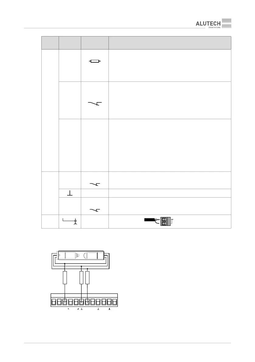
X11
SE
8,2 kOm/
OSE
Door leaf lower margin safety device input;
the contact of the door with an obstacle during closing (activation
of a sensor) causes it to stop moving and then fully open.
In settings (section ‘6. Adjustment’) the following can be
selected, depending on the connected safety device: resistive
sensor / 8.2kOhm or optoelectronic sensor / OSE (g. 3)
PH1
Photo
Safety device input (photocells / g. 4) with a NC contact.
The activation of the device during closing results in stop,
followedby full opening;
if activated during the pause time countdown in the automatic
mode, the pause is reset and the countdown starts anew, or the
pause is reset and the door is closed automatically after 5seconds
(section ‘6. Adjustment’)
PH.T —
Output for automatic operation test (Phototest) of devices,
connected to input ‘PH1’—the operation of the photocells is
checked before movement by short-term disconnection and then
reconnection of the power to the photocells transmitter.
g. 5A—connection of typical photocells to perform Phototest
(‘direct’ Phototest);
g. 5B—connection of photocells with special output ‘TEST’ of the
transmitter (‘inverse’ Phototest).
The activation of the output operation is described in section
‘6.Adjustment’
X9
OP.L
Limit switch
OPEN
Input of the drive opening nal position switch with NC contact
— Common contact for the nal positions switches
CL.L
CLOSE
Input of the drive closing nal position switch with a NC contact
X6
—
External antenna
RG58
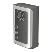
1
PH.T PH1 SE +24V +12V
S
CL
OP
GN WH
BN
TX
RX
Output
COM
+V
TX and RX — optoelectronic
sensor transmitter and rec
GN — green wire
BN — brown wire
WH — white wire
Figure 3. Connection of the optoelectronic safety sensor
for the door leaf lower margin / OSE (Optoelectronic Safety Margin)