CUID400N | CUID400N | CONTROL UNIT CUID400N 47
ELECTRICAL INTERFACES
5. ELECTRICAL INTERFACES
Y
prior to commencing the wiring operation, make sure that the wire is not ‘live’. When
using and installing electric devices (accessories) follow the manuals supplied. Incorrect
connection can result in the failure of the product.
If no devices are connected to terminals ‘PH1’ and ‘
’, ‘S’ and ‘ ’, crossovers should be
installed. If a safety device is connected to the terminals mentioned, remove the crossover.
If a safety device for the door leaf lower margin is not connected, a resistor 8.2kOhm ± 5 %
should be connected to contacts ‘SE’ and ‘ ’, and the working mode with a resistive sensor
should be selected (section ‘6. Adjustment’).
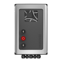
Table 6. Electrical interfaces (g.2)
Socket Contacts
Device
designation
Connection description
X1
L1, L2,
L3, N
—
Electric mains 400V / 50Hz;
L1, L2 and L2—phase contacts, N—neutral contact
X2 W, V, U, PE
M
3~
Drive electric motor;
W, V and U—phase contacts, PE—protection earthing
connectioncontact
X3
FL
230V / max. 100W lamp;
illuminates when the door is moving and also ~ 3seconds before
movement begins (section ‘6.Adjustment’)
N — Neutral contact
SL
230V / max. 100W lamp;
illuminates, when the door is fully open
X11
OP
Open/SBS
Control of the door movement using a device with a NO contact
inthe sequence
(operation mode selection is described in section ‘6.Adjustment’):
• manual mode—the door is opening, when the button,
connected to the input ‘OP’ is pressed;
• semi-automatic mode1:
‘Open—Stop—Close—Stop—Open…’;
• semi-automatic mode2:
‘Open—Stop—Open—Stop…’. Default settings;
• automatic mode—full opening.
Several control devices have parallel connection
CL
Close
Control of the closing using a device with a NO contact:
sequence of commands ‘Close—Stop—Close—Stop…’
— Common contact
S
STOP
Movement stop or movement prohibition by a device with a NC
contact
+12V —
Accessories power output (optoelectronic safety sensor of the door
leaf lower margin);
power voltage 12V DC / max. 50mA
+24V —
Accessories power output;
nominal power voltage 24V DC / max. 100mA