DUAL PULSE 125
STORED ENERGY RESISTANCE WELDING POWER SUPPLY
990-270 2-1
CHAPTER 2
GETTING STARTED
Section I: Planning for Installation
Location
It is recommended that the power supply be installed in a well-ventilated area, free from dirt and
moisture. Air intake for cooling is through the underside, do not place on deep carpet, felt, or foam
pads. Air exits through the left side, allow sufficient clearance so that cooling air may flow properly.
Position the power supply as close as possible to the weld head.
Power Line
CAUTION: Do not connect the line cord at this time.
This power supply was wired for a specific voltage which was marked on the line cord during the
manufacturing process. The standard 125DP is wired for 115 VAC. Re-connection for operation at
another voltage may be made by a qualified technician. Refer to Chapter 5 - Calibration and
Modifications.
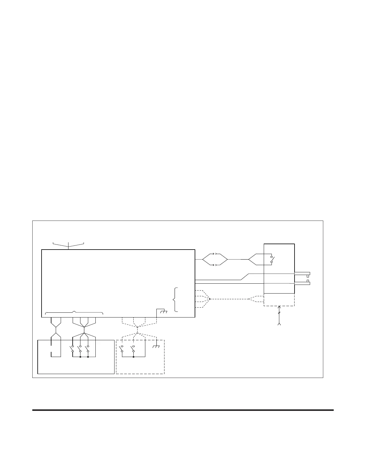
Figure 2-1. Typical set-up diagram for the 125DP showing both Manually
Actuated and Air Actuated Weld Head connections.
125DP
POWER
SUPPLY
115VAC, 15A
50/60 Hz, 1Ø
HOT COM GND
(BLK) (WHT) (GRN)
POWER
EXTERNAL INPUTS
INB GND 2
2
2
1
2
0
GND
1 5 3215
2
2
2
1
2
0
CHARGE
INHIBIT
REMOTE
SCHEDULE
SELECTION
USER SUPPLIED SWITCHING
FOOTSWITCH
LEVEL
1
GND
LEVEL
2
2341
12
INITIATE
AIR
VALVE
DRIVER
24VAC
24/115
RTN
115VAC
AUTO
SENSE
POWER
OUTPUT
MECHANICAL
FIRING
SWITCH
1
2
3
4
(SEE NOTE 3)
AIR
SOLENOID
24/115VAC
ELECTRODES
WELD CABLES
(SEE NOTE 2)
1
2
(SEE NOTE 1)
FORCE
FIRING
SWITCH
WELD
HEAD
NOTES:
1 For non-force fired weld head opertion,
short pins 1 and 2 on the Firing Switch
connector.
2 Tie the weld cables together.
3. Dashed lines represent air actuated weld
head connections.


 To Next Page