CHAPTER 5: MAINTENANCE
DUAL PULSE 125
STORED ENERGY RESISTANCE WELDING POWER SUPPLY
5-2 990-270
Calibration
The 125DP should not require any regular adjustments. Use the following procedure as a guideline to
check the calibration. Care should be taken not to make unnecessary adjustments. Do not hesitate to
call the Amada Miyachi America Repair Department with any questions.
1. Push the POWER Switch to OFF. Remove the cover.
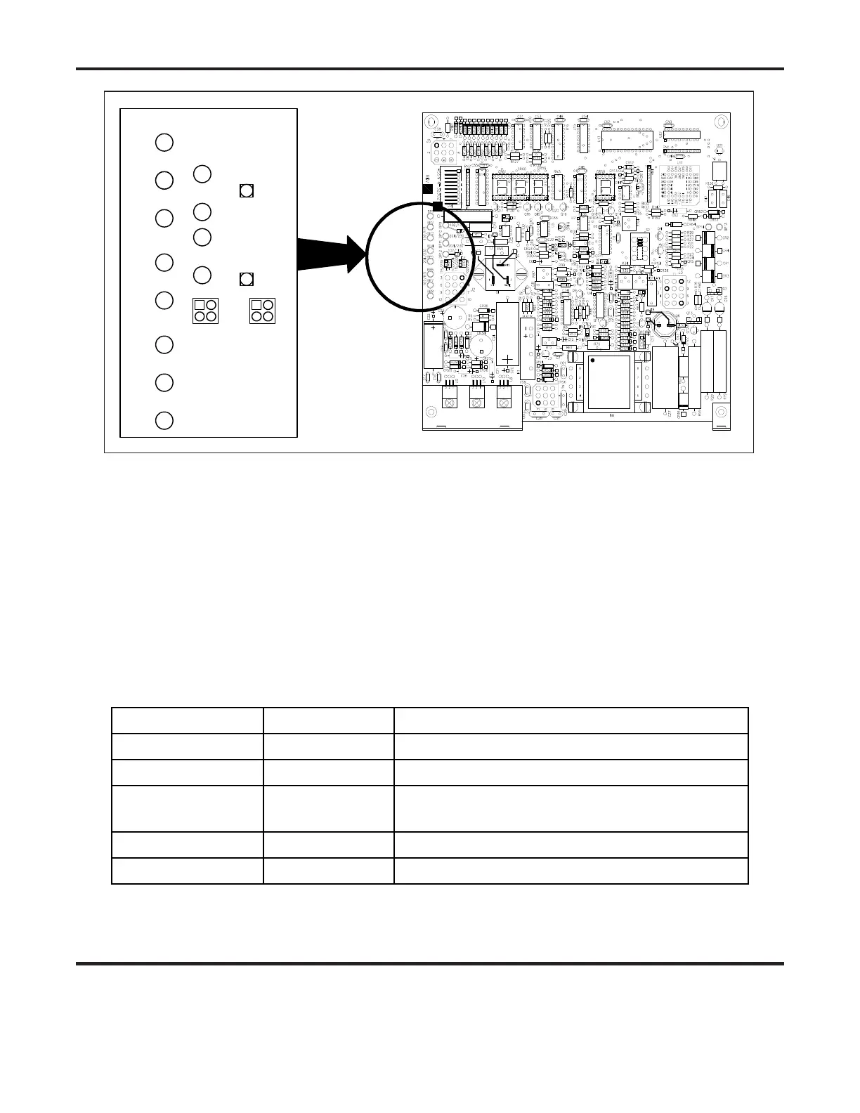
2. Push to POWER Switch to ON. Use a Digital Voltmeter to check the output of the power supplies.
Use a Digital Voltmeter to check the output of the power supplies. Using TP0 as ground, the
voltages should be as follows:
Nominal Output Test Point Acceptable Range
-15 volts U9, Pin 3 -14.25 to -15.75 volts
+15 volts U8, Pin 3 +14.25 to +15.75 volts
Comm Supply CR35 Cathode+ +101.50 to +106.50 volts (115V input)
* NOTE: With Line Voltage at Nominal, ± 0.1V.
+5 volts U10, Pin 3 +4.75 to +5.25 volts
+15 volts REF U2, Pin 1 +14.25 to +15.75 volts
Figure 5-1. Line Voltage pins on Control Board
BP1
BP2
BP3
BP4
BP5
BP6
BP7
BP8
102/115204/230102/115
BP9
BP10BP11BP12
102/115
204/230
204/230
102/115
E1
E2
115/230
102/204
115/230
102/204
 Loading...