11
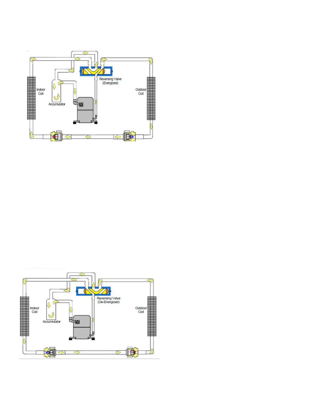
When the heat pump is in the cooling cycle, it operates
exactly as an Air Conditioner Unit. See Figure 8: HEAT
PUMP COOLING SCHEMATIC
The heat pump operates in the heating cycle by redirecting
refrigerant ow through the refrigerant circuit external to the
compressor. This is accomplished with the reversing valve.
Hot discharge vapor from the compressor is directed to
the indoor coil (evaporator on the cooling cycle) where
the heat is removed, and the vapor condenses to liquid.
It then goes through the expansion device to the outdoor
coil (condenser on the cooling cycle) where the liquid is
evaporated, and the vapor goes to the compressor.
When the solenoid valve coil is operated either from
heating to cooling or vice versa, the piston in the reversing
valve to the low pressure (high pressure) reverse positions
in the reversing valve. The following gure, FIGURE 9:
HEAT PUMP HEATING SCHEMATIC, shows a schematic
of the heat pump in the heating cycle.
For Heat Pump units, the expansion devices are Thermal
Expansion Devices (TXV) and perform the same function
on the heating cycle as on the cooling cycle. The TXVs
also act as check valves to allow for the reverse of
refrigerant ow.
When the heat pump is on the heating cycle, the outdoor
coil is functioning as an evaporator. The temperature
of the refrigerant in the outdoor coil must be below the
temperature of the outdoor air in order to extract heat from
the air. Thus, the greater the dierence in the outdoor
temperature and the outdoor coil temperature, the greater
the heating capacity of the heat pump. This phenomenon
is a characteristic of a heat pump. It is a good practice to
provide supplementary heat for all heat pump installations
in areas where the temperature drops below 45° F. It is
also a good practice to provide sucient supplementary
heat to handle the entire heating requirement should
there be a component failure of the heat pump, such as a
compressor, or refrigerant leak, etc.
Since the temperature of the liquid refrigerant in the
outdoor coil on the heating cycle is generally below
freezing point, frost forms on the surfaces of the
outdoor coil under certain weather conditions of
temperature and relative humidity. Therefore, it is
necessary to reverse the ow of the refrigerant to provide
hot gas in the outdoor coil to melt the frost accumulation.
This is accomplished by reversing the heat pump to the
cooling cycle. At the same time, the outdoor fan stops
to hasten the temperature rise of the outdoor coil and
lessen the time required for defrosting. The indoor blower
continues to run, and the supplementary heaters are
energized.
During operation the power to the circuit board is controlled
by a temperature sensor, which is clamped to a feeder tube
entering the outdoor coil. Defrost timing periods of 30,60
and 90 minutes may be selected by setting the circuit
board jumper to 30, 60 and 90 respectively. Accumulation
of time for the timing period selected starts when the
sensor closes (approximately 30 ± 5°F), and when the wall
thermostat calls for heat. At the end of the timing period,
the unit’s defrost cycle will be initiated provided the sensor
remains closed. When the sensor opens (approximately
60°± 5°F), the defrost cycle is terminated and the timing
period is reset. If the defrost cycle is not terminated due to
the sensor temperature, a twelve-minute override interrupts
the unit’s defrost period.
TESTING DEFROST CONTROL
 Loading...