14
Replace adjustment cap. Wait a minimum of 10 minutes
between adjustments to allow time for the TXV and pres-
sures to stabilize.
All package units with xed orice devices are charged
using the superheat method at the compressor suction line.
To increase super heat, remove charge and to decrease
super heat, add charge. After superheat is adjusted, it is
recommended to check unit subcooling at the condenser
coil liquid line. See FIGURE 13: DESIGN SUPERHEAT
AND SUBCOOL table for targets on each model.
Single Stage Cooling Application: Refer to the Design Su-
perheat & Subcooling table
Two-Stage Cooling Application: Run unit on Low Stage
cooling and refer to Design Superheat & Subcooling table.
1. Purge gauge lines. Connect service gauge manifold
to access ttings. Run system at least 10 minutes to
allow pressure to stabilize.
2. Temporarily install thermometer on liquid (small) line
near liquid line access tting with adequate contact
and insulate for best possible reading.
3. Check subcooling and superheat. System should
have a subcooling and superheat within the range
listed on the Design Superheat and Subcooling
table.
a. If subcooling and superheat are low, adjust TXV
superheat, then check subcooling.
To adjust superheat, turn the valve stem
clockwise to increase and counterclockwise to
decrease.
b. If subcooling is low and superheat is high, add
charge to raise subcooling then check superheat.
c. If subcooling and superheat are high, adjust TXV
valve superheat, then check subcooling.
d. If subcooling is high and superheat is low, adjust
TXV valve superheat and remove charge to lower
the subcooling.
Do NOT adjust the charge based
on suction pressure unless there is a gross
undercharge.
4. Disconnect manifold set, installation is complete.
Model
Superheat
±2°F
Subcooling
±1°F
Expansion
Device
Cooling
Stage
Outdoor
ambient (°F)
APHM52441 10 6 TXV Low 82
APHM53041 5 9 TXV Low 82
APHM53641 11 7 TXV Low 82
APHM54241 8 7 TXV Low 82
APHM54841 8 9 TXV Low 82
Refer to the specication manual for heater kit match up
and Heater Kit Electrical Data.
This series of electric cooling and heat pump package
equipment is designed to accept a eld installed electric
heat kit. The unit is equipped to easily install the
HKR/HKP Series Electric Heat Kit. Full Installation
Instructions are included in this kit. Please use this
document for guidance in eld equipping the package
unit with electric heat. Choose the heat kit that ts the
application for the specic installation. Permanently mark
the unit’s nameplate with the model being installed. High
and low voltage connections are detailed in the heat kit
instructions. Indoor Blower motor speed tap selection may
need to be modied to accommodate normal continuous
operation to prevent a nuisance trip. See below FIGURE
14: ELECTRIC HEAT kW.
8
APHM52441 X X X
APHM53041 X X X X
APHM53641 X X X X
APHM54241 X X X X
APHM54841 X X X X X
The Self-Contained Package Air Conditioner and Heat
Pump should operate for many years without excessive
service calls if the unit is installed properly. However,
it is recommended that the homeowner inspect the unit
before a seasonal start up. The coils should be free of
debris so adequate airow is achieved. The return and
supply registers should be free of any obstructions. The
lters should be cleaned or replaced. These few steps
will help to keep the product up time to a maximum. The
Troubleshooting Chart (see Appendix) should help in
identifying problems if the unit does not operate properly.
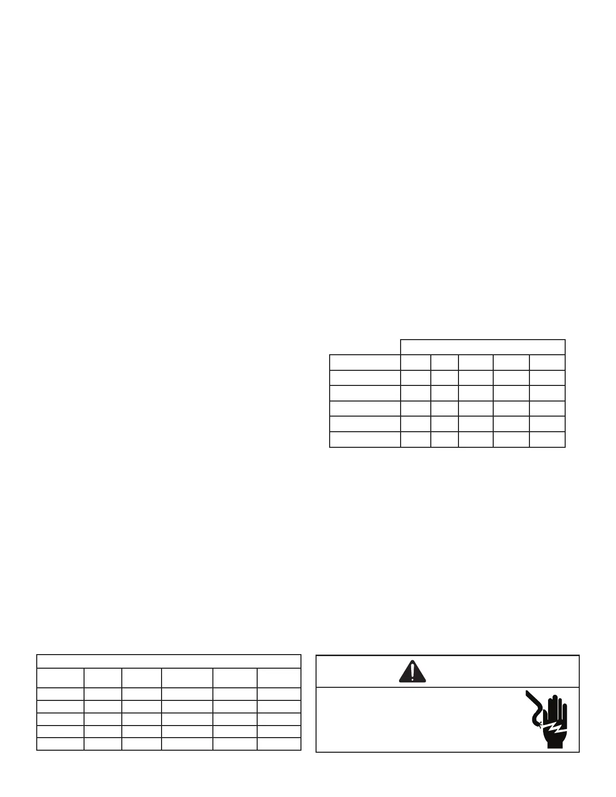
WARNING
 Loading...