8
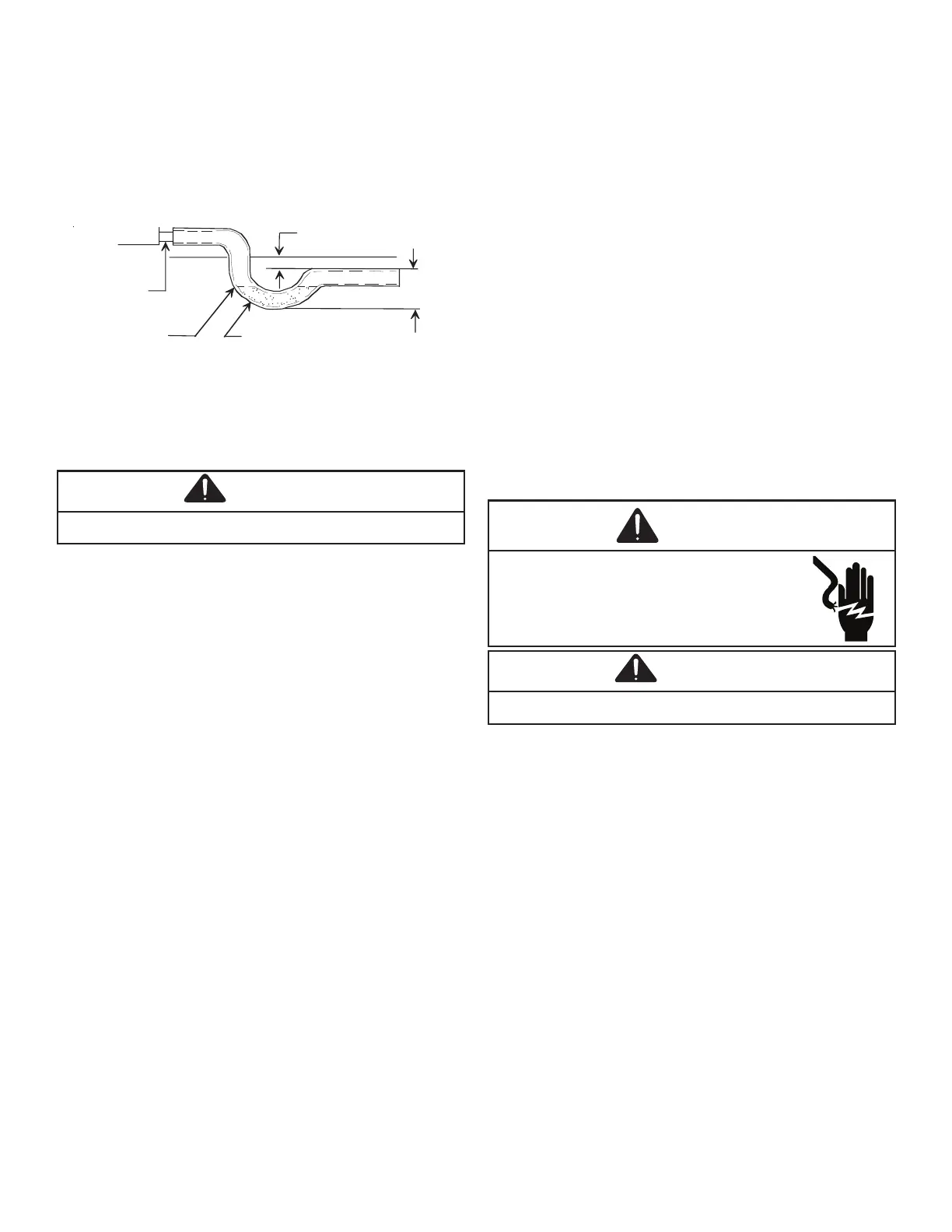
The condensate drain connection of the evaporator is a
¾” NPT half coupling. A trap must be provided to have
proper condensate draining. Install condensate drain trap
as shown in FIGURE 7: CONDENSATE DRAIN TRAP
PLUMBING. Ensure drain connection is 3/4” or larger. Do
not operate unit without trap and ensure unit is level or
slightly inclined toward drain.
2" Minimum
3" Minimum
A Positive Liquid Seal
Is Required
Flexible
Tubing-Hose
Or Pipe
Drain
Connection
Unit
CAUTION
All wiring should be made in accordance with the National
Electrical Code. The local power company should
be consulted to determine the availability of sucient
power to operate the unit. The voltage, frequency, and
phase at the power supply should be checked to make
sure it corresponds to the unit’s RATED VOLTAGE
REQUIREMENT.
Install a branch circuit fused disconnect near the unit, in
accordance with the N.E.C. or local codes. Wire sizes and
overcurrent protection should be determined from the unit
nameplate ampacity and in accordance with N.E.C. and
local building codes. Under no circumstances should wiring
be sized smaller than is recommended by either of these
two sources.
Fuses smaller than that recommended on the unit
nameplate could result in unnecessary fuse failure or
service calls. The use of protective devices of larger size
than indicated could result in extensive damage to the
equipment. The manufacturer bears no responsibility for
damage caused to equipment due to the use of larger than
the recommended size protective devices.
All units have undergone a run test prior to packaging for
shipment. This equipment has been started at minimum
rated voltage and checked for satisfactory operation.
Do not attempt to operate this unit if the voltage is not
within the minimum and maximum voltages shown on the
nameplate.
The units are designed for operation at the voltage,
frequency, and phase as shown on the rating plate. All
internal wiring in the unit is complete. It is necessary to
bring in the power supply to the contactor as shown on the
unit wiring diagram which is supplied with each unit. The
low voltage wiring must be connected between the unit
control panel and the room thermostat.
All exterior wiring must be within approved weatherproof
conduit. The unit must be in
accordance with local codes, or in absence of local codes
with N.E.C. ANSI/NFPA NO. 70-1984 or latest edition by
using ground lug in the control box.
DO NOT EXCEED THE MAXIMUM OVERCURRENT
DEVICE SIZE SHOWN ON UNIT DATA PLATE.
Fuses or HACR type circuit breakers may be used where
codes permit.
WARNING
CAUTION
Single phase – Connect two leads to terminals L1 & L2 in
the electrical control section, using wire sizes specied in
wiring table.
Heat Pumps – Connect 24V wires from the thermostat to
the corresponding wires in the control box using No. 18
AWG as follows:
 Loading...