7
Ducting work should be fabricated by the installing
contractor in accordance with local codes. Industry
manuals may be used as a guide when sizing and
designing the duct system-such as NESCA (National
Environmental Systems Contractors Association, 1501
Wilson., Arlington, Virginia 22209).
The unit should be placed as close as possible to the
space to be air-conditioned allowing clearance dimensions
as indicated. Ducts should run as directly as possible
to supply and return outlets. Use of non-ammable
weatherproof exible connectors on both supply and return
connections at the unit to reduce noise transmission is
recommended.
It is preferable to install the unit on the roof of the structure
if the registers or diusers are in the wall or ceiling. A slab
installation is recommended when the registers are low on
the wall or in the oor.
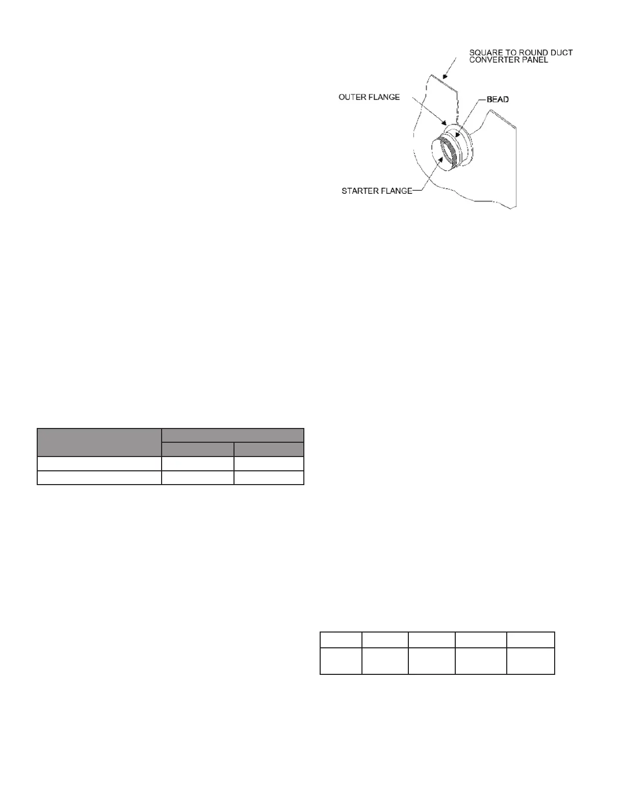
The return and supply ttings are to be attached at
the unit to a suitable square to round duct converter.
Your distributor has a factory designed square to round
converter transition. The model #’s of these kits are as
follows in the table below. (See Specication Sheets for
Dimension details).
The SQRPG101, SQRPG102, and SQRPG103 t up to
the Return and Supply Downow vents having dimensions:
Return (22 ¾” x 12 ¼”) and Supply (22 ¼” x 14 ¾”). The
SQRPGH101, SQRPGH102, and SQRPGH103 t up to
the Horizontal Return and Supply downow vents having
dimensions: Medium Chassis (16 ½” x 16 ½”) and Large
Chassis (18 ½” x 18 ½”). The Medium Chassis kits
transition to a 16” Diameter and the Large Chassis kits
transition to an 18” Diameter
(equivalent diameter, opening is oval) on the return. The
collars are to be slipped into the openings, and the anges
bent around the converter. The square to round converter
is attached to the anges of the square duct openings.
The exible duct is then clamped on to the collars. Once
the duct is axed to the unit, seal the collars and anges
with a proper waterproof sealant. SEE FIGURE 6:
MANUFACTURED HOME MODIFICATION KIT.
It is strongly encouraged to use appropriately sized ducts
based upon the CFM for your application (unit’s CFM). If
duct sizing through industry manuals or air duct calculators
requires larger ducts than converter openings, run larger
duct size up to unit converter openings and reduce with a
reducer duct tting or transition right at the unit.
A suitable plenum or square duct must be constructed. The
duct cross-sectional area should be determined by industry
duct sizing manuals or air duct calculators.
On ductwork exposed to outside air conditions of
temperature and humidity, use an insulation with a good
K factor, and a vapor barrier. Industry practices should be
followed. Balancing dampers are recommended for each
branch duct in the supply system. Ductwork should be
properly supported from the unit.
Filters are not provided with unit and must be supplied
and externally installed in the return duct system by the
installer. A eld-installed lter grille is recommended for
easy and convenient access to the lters for periodic
inspection and cleaning. When installing lters, ensure
the air ow arrows on the lter are pointing toward the
circulator blower. For unit lter size information, see table
below for recommended lter size.
UNIT
Min.
Filter
Size
(1)20X20X1
(1)20X25X1 (1)25X25X1 (2)20X20X1
 Loading...