Component Testing Procedures
WARNING
To avoid risk of electrical shock, personal injury, or death, disconnect power to oven and discharge capacitor
before servicing, unless testing requires it.
20 RS2230003 Rev. 2
Illustration Component Testing Results
1
2
3
4
7
6
5
8
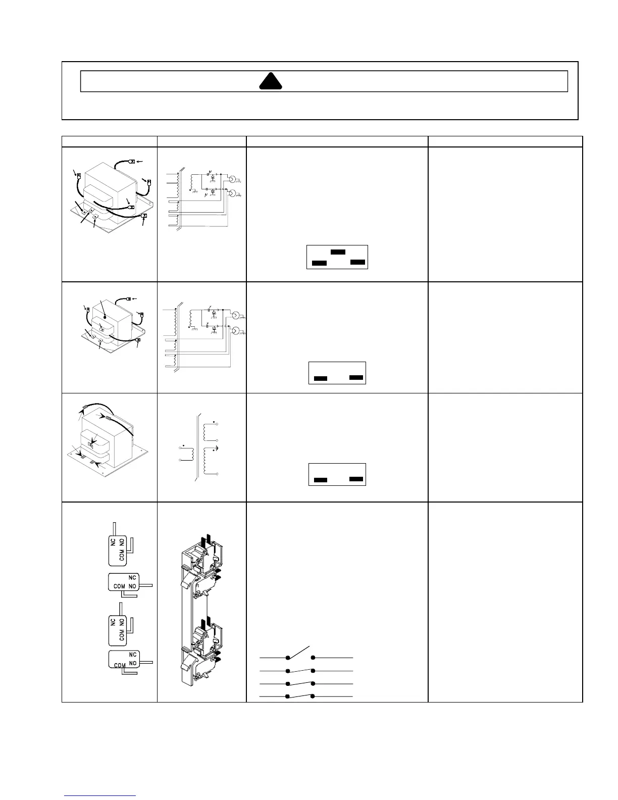
Terminal 1
−
Common
Terminal 2
−
230 V
Terminal 3
−
208 V
Transformer
# 4
1
3
2
5
6
# 7
8
1.0 F
-300 MA
-300 MA
1.0 F
CRC21T2, CRC18T2,
CRC18T2SD
FSC18VP
Discharge Capacitors
Remove all wires from terminals.
Measure resistance from:
Terminal 1 to 2
Terminal 1 to 3
Terminal 5 to 6
Terminal 7 to 8
Terminal 4 to Ground screw on transformer
Terminal 4 to any other terminal
Gray
Violet
Red
12
3
1.0
Ω
Less than 1
Ω
Less than 1
Ω
Less than 1
Ω
30
Ω
Infinite resistance should be
indicated, if not replace transformer.
1
2
4
7
6
5
8
Ground
Terminal 1
−
Common
Terminal 2
−
120 V
Transformer
# 4
1
2
# 5
# 6
# 7
8
1.0 F
1.0 F
-300 MA
-300 MA
CRC12T2, CRC12T,
FSC12VP
Discharge Capacitor
Remove all wires from terminals, and
measure resistance from:
Terminal 1 to 2
Terminal 5 to 6
Terminal 7 to 8
Terminal 4 to Ground screw on transformer
Terminal 4 to any other terminal
Red
12
Gray
Less than 1
Ω
Less than 1
Ω
Less than 1
Ω
40
Ω
Infinite resistance should be
indicated, if not replace transformer.
4
2
1
6
5
Terminal 1
−
120 V
Terminal 2
−
Common
Transformer
4
1
2
5
6
CRC10T2, CRC10T,
FSC10VP
Discharge Capacitor
Remove all wires from terminals, and
measure resistance from:
Terminal 1 to 2
Terminal 5 to 6
Terminal 4 to Ground screw on transformer
Terminal 4 to any other terminal
Red
12
Gray
Less than 1
Ω
Less than 1
Ω
78
Ω
Infinite resistance should be
indicated, if not replace transformer.
Monitor
Primary
Logic
Secondary
Interlock switch
assembly
*
Disconnect wires to switch.
With door open measure resistance from:
Terminal C to NC Monitor
Terminal C to NO Primary
Terminal C to NO Logic
Terminal C to NO Secondary
With door closed measure resistance from:
Terminal C to NC Monitor
Terminal C to NO Primary
Terminal C to NO Logic
Terminal C to NO Secondary
Door Closed
C
C
C
C
NC
NO
NO
NO
Primary
Secondary
Monitor
Logic
Indicates continuity
Infinite
Infinite
Infinite
Infinite
Indicates continuity
Indicates continuity
Indicates continuity
* NOTE:
The two lower switches on the switch assembly (logic and secondary) may be reversed. Both switch
configurations are acceptable.
 Loading...