SYSTEM OPERATION
19
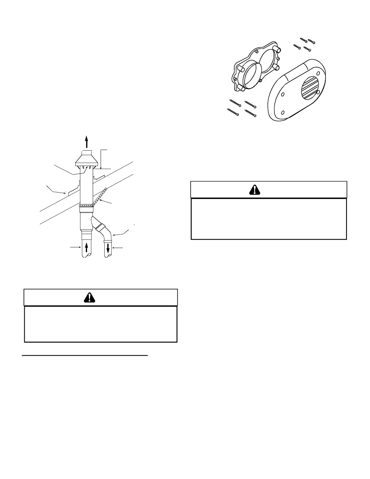
1. Determine the best location for the termination kit. Roof
termination is preferred since it is less susceptible to dam-
age, has reduced intake contaminants and less visible
vent vapors. For side termination, consideration should
be given to:
a. Possible damage from the vapors to plants/shrubs,
other equipment and building materials
b. Possible damage to the terminal from foreign objects
c. Wind eects that may cause recirculation of ue
products, debris or light snow
d. Visible vent vapors.
Maintain 12" (18" for Canada)
minimum clearance above highest
anticipated snow level. Maximum of
24" above roof.
Combustion Air
Roof Boot/Flashing
(Field Supplied)
Support (Field Supplied)
45 Elbow
(Field Supplied)
Combustion Air
Vent
WARNING
D
N PERAE E RNACE WI E RAIN CAP REMVED AS
RECIRCLAIN E LE GASES MA CCR
W
AER MA ALS
CLLEC INSIDE E LARGER CMSIN AIR PIPE AND LW E
RNER ENCLSRE
AILRE LLW IS WARNING CAN RESL IN
PRPER DAMAGE EQIPMEN DAMAGE PERSNAL INJR R DEA
This (sidewall only) vent kit is to be used with 2” - 3” vent
systems. The vent kit must terminate outside the structure and
may be installed with the intake and exhaust pipes located
side-by side or with one pipe above the other. This kit is NOT
intended for use with single pipe (non-direct vent) installations.
A condensing gas furnace achieves its high level of eciency
by extracting almost all of the heat from the products of
combustion and cooling them to the point where condensation
takes place. The condensate which is generated must be
piped to an appropriate drain location.
WARNING
I
N PRIG PLW INSALLAINS E DRAIN RAP MS E MNED N
E PPSIE SIDE E NI RM E JNCIN X
IS WILL
RED
CE E R
ISK
WAER
RE
ACING
E JNC
IN
X IN
E EV
EN
A LCKED DRAIN CNDIIN
AILRE LLW ESE INSRCINS
CAN RESL IN PSSILE PRPER DAMAGE PERSNAL INJR R DEA
DE ELECRICAL SCK
• • If the drain line is routed through an area which may
see temperatures near or below freezing, precautions
must be taken to prevent condensate from freezing
within the drain line.
• • If an air conditioning coil is installed with the furnace,
a common drain may be used. An open tee must
be installed in the drain line, near the cooling coil, to
relieve positive air pressure from the coil’s plenum.
This is necessary to prohibit any interference with the
function of the furnace’s drain trap.
Horizontal installations require 5.5” under the furnace
to accommodate the drain trap. The horizontal furnace
must be installed with ¾” slope from back to front to permit
condensate ow towards the front of the furnace.
When installing a *MES9* horizontally with the left side
down, there are two options for connecting the vent pipe to
the furnace.
Option 1
Venting may be connected to the furnace vent pipe tting on
the original top (now the end) of the furnace.
Option 2
The internal vent pipe and elbow may be removed from the
furnace to permit the vent to exit the top (original side) of
the furnace. If this option is used, an RF000142 Vent-Drain
coupling must be used to keep condensate from collecting
in the inducer assembly.
 Loading...