SYSTEM OPERATION
20
To install the drain, refer to the following instructions and
illustration.
COMBUSTION AIR INTAKE PIPE OPTIONS:
The RF000142 coupling can be secured directly to the
furnace intake coupling if condensation is occurring in the
combustion air inlet pipe. If the RF000142 is used on the
combustion air inlet, it must be installed with the arrow
pointing up. It should be noted, the combustion air will
actually be moving in a direction opposite of the arrow on the
RF000142 coupling.
Alternatively a tee may be used in the combustion air
intake pipe for the same purpose. If either option is used,
a eld supplied trapped drain tube, free-draining to proper
condensate disposal location must be present. A loop in the
drain tube can serve as a trap. The unused RF000142 drain
tting should be capped.
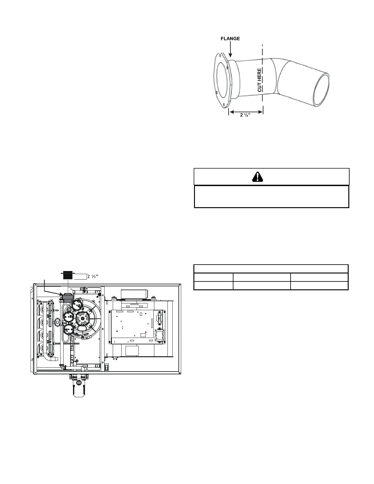
1. Remove screws from vent ange.
2. Remove internal elbow and vent pipe.
3. Cut pipe 2 1/2” from ange.
4. Remove cabinet plug adjacent to inducer outlet and
install an original cabinet vent hole.
5. Install RF000142 coupling on inducer outlet.
6. Install anged vent section removed in step 2 and se-
cure with clamps.
7. Secure ange to cabinet using screws removed in step
1.
Insert flange. Cut 2 ½” long.
R 000142F
The furnace rating plate includes the approved furnace gas
input rating and gas types. The furnace must be equipped
to operate on the type of gas applied. This includes any
conversion kits required for alternate fuels and/or high altitude.
PREVEN NRELIALE PERAIN R EQIPMEN DAMAGE E INLE
GAS SPPL PRESSRE MS E AS SPECIIED N E NI RAING PLAE
WI ALL ER SELD GAS IRED APPLIANCES PERAING
Inlet gas supply pressures must be maintained within the
ranges specied below. The supply pressure must be constant
and available with all other household gas red appliances
operating. The minimum gas supply pressure must be
maintained to prevent unreliable ignition. The maximum must
not be exceeded to prevent unit overring.
Natural Gas Minimum: 4.5" w.c. Maximum: 10.0" w.c.
Propane Gas Minimum: 11.0" w.c. Maximum: 13.0" w.c.
When this furnace is installed at high altitude, the appropriate
High Altitude orice kit must be applied. This is required due
to the natural reduction in the density of both the gas fuel and
combustion air as altitude increases. The kit will provide the
proper design certied input rate within the specied altitude
range.
High altitude kits are purchased according to the installation
altitude and usage of either natural or propane gas. Refer to
the product Specication Sheet or the Accessory Matrix in this
Manual for a tabular listing of appropriate altitude ranges and
corresponding manufacturer’s high altitude (Natural, Propane
gas, and/or Pressure Switch) kits.
Do derate the furnace by adjusting the manifold pressure
to a lower pressure than specied on the furnace rating plate.
The combination of the lower air density and a lower manifold
pressure will prohibit the burner orice from drawing the proper
amount of air into the burner. This may cause incomplete
combustion, ashback, and possible yellow tipping.
In some areas the gas supplier may articially derate the gas
in an eort to compensate for the eects of altitude. If the
gas is articially derated, the appropriate orice size must be
 Loading...