SYSTEM OPERATION
21
determined based upon the BTU/ft
3
content of the derated
gas and the altitude. Refer to the National Fuel Gas Code,
NFPA 54/ANSI Z223.1, and information provided by the gas
supplier to determine the proper orice size.
A dierent pressure switch may be required at high altitude
regardless of the BTU/ft
3
content of the fuel used. Refer to the
product Specication Sheet or Technical Manual for a tabular
listing of appropriate altitude ranges and corresponding
manufacturer’s pressure switch kits.
WARNING
P
SSILE PRPER DAMAGE PERSNAL INJR R DEA MA CCR I
E CRREC CNVERSIN KIS ARE N INSALLED
E APPRPRIAE KIS
MS E APPLIED INSRE SAE AND PRPER RNACE PERAIN
A
LL
CNVERSINS MS E PERRMED A QALIIED INSALLER R SERVICE
AGENC
This unit is configured for natural gas. The appropriate
manufacturer’s propane gas conversion kit, must be applied
for propane gas installations.
**ES9* models using a White-Rodgers 36J22 single stage
valve use LPM-07 LP Conversion Kit.
GAS VALVE
This unit is equipped with a 24 volt gas valve controlled
during furnace operation by the integrated control module.
As shipped, the valve is congured for natural gas. The valve
is eld convertible for use with propane gas by using the
appropriate propane gas conversion kit. Taps for measuring
the gas supply pressure and manifold pressure are provided
on the valve.
The gas valve has a manual ON/OFF control located on
the valve itself. This control may be set only to the “ON” or
“OFF” position. Refer to the Lighting Instructions Label or the
“Putting the Furnace Into Operation” section of this manual or
the installation instructions for use of this control during start
up and shut down periods.
AVID PSSILE NSAISACR PERAIN R EQIPMEN DAMAGE
DE NDERIRING EQIPMEN SE E PRPER SIE
NARAL/PRPANE GAS PIPING NEEDED WEN RNNING PIPE RM E
MEER/ANK E RNACE
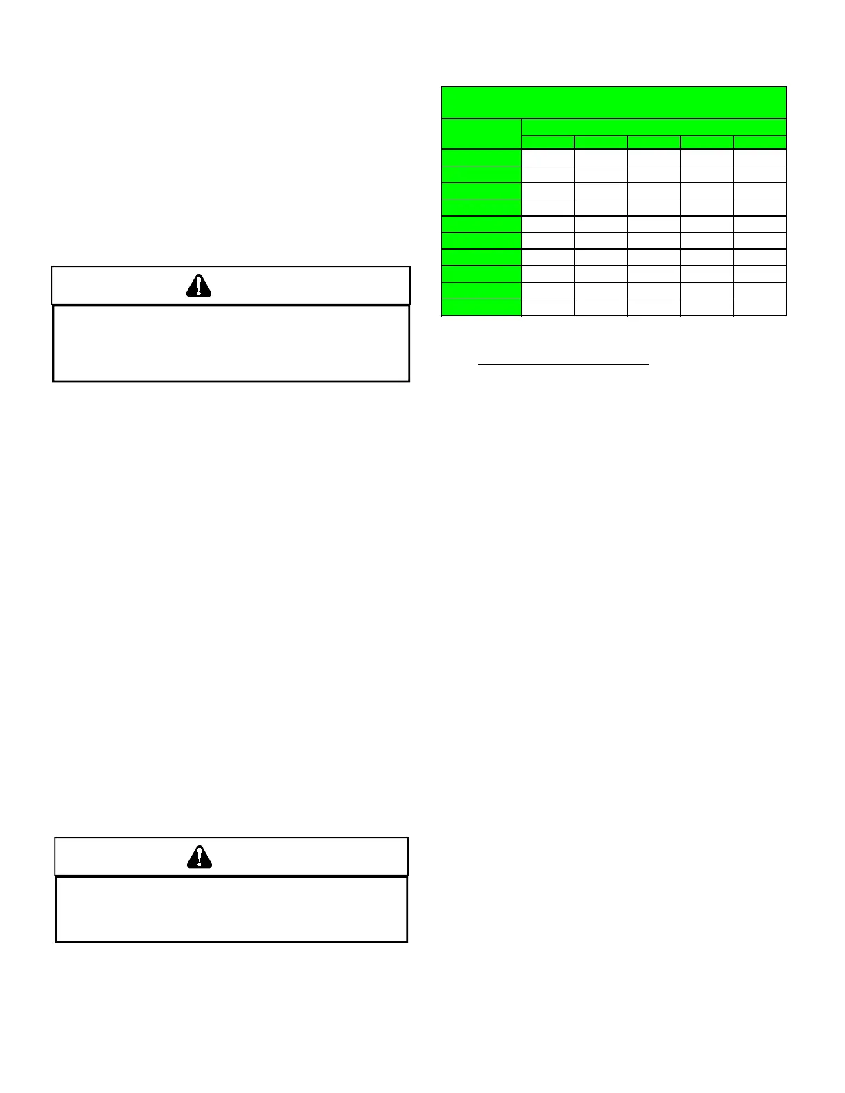
The gas piping supplying the furnace must be properly sized
based on the gas ow required, specic gravity of the gas,
and length of the run. The gas line installation must comply
with local codes, or in their absence, with the latest edition of
the National Fuel Gas Code, NFPA 54/ANSI Z223.1.
Length of
Nominal Black Pipe Size
Pipe in Feet 1/2" 3/4" 1" 1 1/4" 1 1/2"
132 278 520 1050 1600
92 190 350 730 1100
73 152 285 590 980
63 130 245 500 760
56 115 215 440 670
50 105 195 400 610
46 96 180 370 560
43 90 170 350 530
40 84 160 320 490
38 79 150 305 460
CFH =
(Pressure 0.5 psig or less and pressure drop of 0.3" W.C.; Based on 0.60
Specific Gravity Gas)
BTUH Furnace Input
Heating Value of Gas (BTU/Cubic Foot)
To connect the furnace to the building’s gas piping, the installer
must supply a ground joint union, drip leg, manual shuto
valve, and line and ttings to connect to gas valve. In some
cases, the installer may also need to supply a transition piece
from 1/2” pipe to a larger pipe size.
The following stipulations apply when connecting gas piping.
Refer to the following gures for typical gas line connections
to the furnace.
1. Use black iron or steel pipe and ttings for the building
piping.
2. Use pipe joint compound on male threads only. Pipe
joint compound must be resistant to the action of the
fuel used.
3. Use ground joint unions.
4. Install a drip leg to trap dirt and moisture before it can
enter the gas valve. The drip leg must be a minimum of
three inches long.
5. Install a 1/8” NPT pipe plug tting, accessible for test
gage connection, immediately upstream of the gas
supply connection to the furnace.
6. Use two pipe wrenches when making connection to
the gas valve to keep it from turning. The orientation of
the gas valve on the manifold must be maintained as
shipped from the factory.
7. Install a manual shuto valve between the gas meter
and unit within six feet of the unit. If a union is installed,
the union must be downstream of the manual shuto
valve, between the shuto valve and the furnace.
8. Tighten all joints securely.
 Loading...