1. Introduction
The ACN-ML MasterLockit combines the state of the art, high-accuracy Lockit timecode technology by
Ambient with advanced metadata administration and sharing over the Lockit Network.
It implements a dual-system design through a full-featured ACN Lockit circuitry with adapted software
for no-compromise, fail-safe timecode integrity and a powerful multi-core CPU platform for
unsurpassed mobile metadata processing. Providing local and set-spanning, line-level accurate
timecode and metadata over ACN plus WiFi routing for Lockit Network apps and certified devices it can
work both autonomously as hub or satellite in your timecode and metadata network.
An integrated backup cell with automatic charge-when-supplied will keep both systems alive for even
lengthy set reconstructions or breaks and secure a coordinate shutdown on power drain.
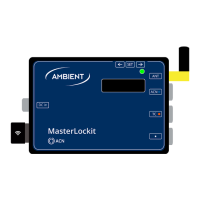
2. Package Contents
• ACN-ML MasterLockit
• ACN Antenna (attached to ACN-ML)
• USB WiFi Stick (attached to ACN-ML)
• Manual
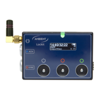
3. Powering
The ACN-ML can be powered by 6 to 24 Volts DC via either indicated Hirose 4-pin connectors, pin 1
carrying GND pin 4 positive voltage. The connectors are configured loop-through. Only apply power
through one socket.
Upon applying external power the internal battery will automatically be charged. The power source
must be capable of supplying 1.5A for charging the internal battery.
While in operation, the active power source is indicated in the upper right corner of the display, EXT
means external power is applied with appropriate voltage and current, whereas INT indicates that the
unit is running on its integrated backup cell.
Typical values in operation with backup cell charged/in charging:
~ 500mA/850mA @ 6V DC
~ 250mA/400mA @ 12V DC
~ 150mA/200mA @ 24V DC
The MasterLockit must only be powered from either of its 4-pin Hirose sockets. The operating voltage
range is 6-24V DC regulated, with pin 1 being GND and pin 4 carrying V+ per the industry standard.
Note: The two power sockets are wired in parallel for loop through of voltage. It is mandatory that only
one socket must carry supply voltage at any given time!
With power applied, red LED over the display will slowly blink to indicate charging of the integrated
backup cell. Fully charged, red and green LED will be lit permanently. The battery will keep the unit
powered for a couple of hours, depending on the processing load of the unit.