S System
-10
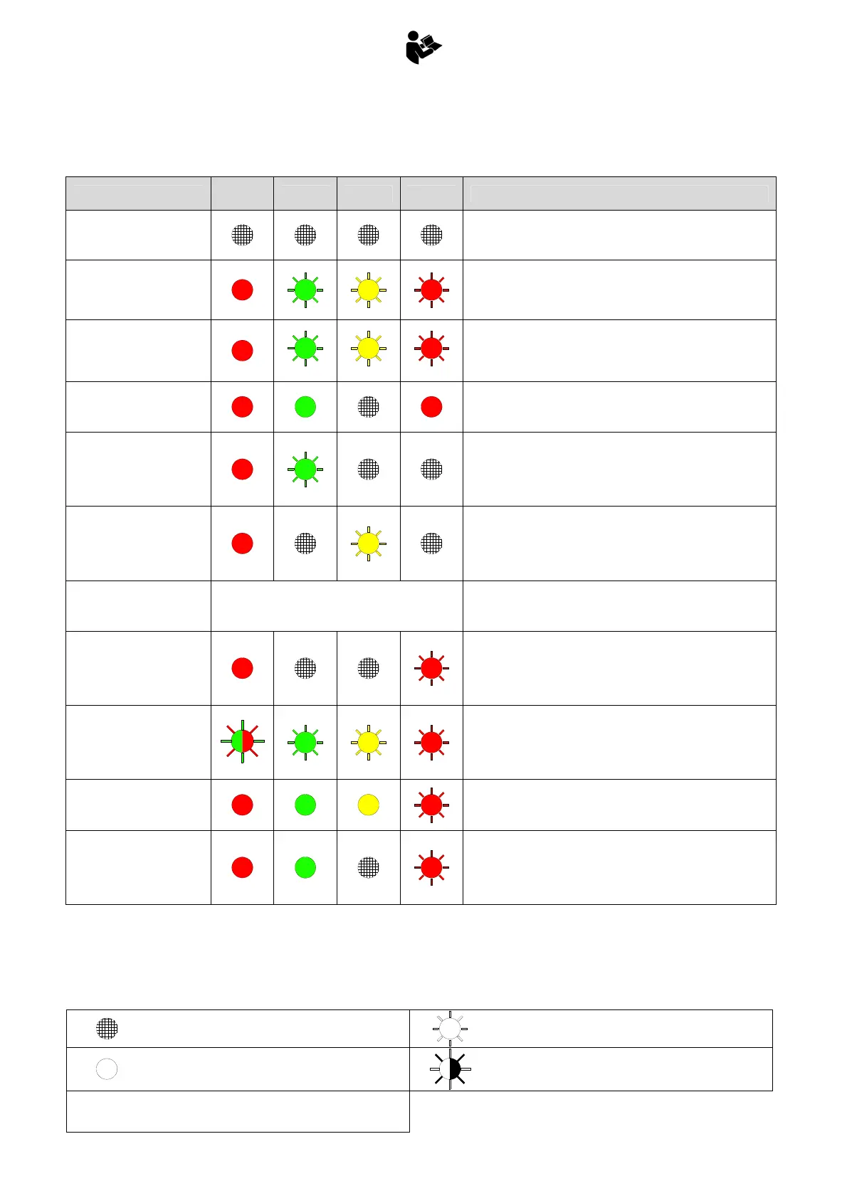
A.5 ALARM SIGNALS
Legend
ALARM DESCRIPTION
STAB
OK
PWR 90% 100% PROBLEM RESOLUTION
No power to system
- Check the fuse on the power supply cable (F01-5A)
- Ensure the emergency stop button is not pressed
- Check for power on the supply cable
Pressure transducer
disconnected
- Check the pressure transducer
- Check the pressure transducer’s cable
- Connect a 2Kohm resistor across connector X3 to simulate the
presence of the transducer
Pressure transducer input
short-circuited
1
2
3
- Check the pressure transducer
- Check the pressure transducer’s cable
- Connect a 2Kohm resistor across connector X3 to simulate the
presence of the transducer
Electronic board not
programmed
- Recalibrate the moment limiter
Extension retract switch
open during system startup
- Check switch “L.S. Extensioni IN” on the control valve
- Check the cable for switch “L.S. Extensioni IN”
- Check for voltage on PIN 3, connector X2
- Connect PIN3 to PIN4, connector X2, to simulate the presence
of the switch
Central switch open during
system startup
- Check the central switch and the function of the levers on the
control valve
- Check the cable to the central switch
- Connect PIN1 to PIN2 on connector X2 to simulate the
presence of the switch
YVH1 short-circuited
No signals
System protection mode active
- Check the condition of the cable connected to the emergency
valve
- Check the emergency valve solenoid
Stabilizer movement switch
open during system startup
- Check switch “controllo stab.” on the control valve
- Check the cable to switch “controllo stab.”
- Check for voltage on PIN1, connector X5
- Connect PIN1 to PIN4, connector X5, to simulate the presence
of the switch
Extension retract switch,
central switch, and
stabilizer movement switch
all open during system
startup
- Check sensors
- Check cables
YVH1 powered (high)
contrary to control system
logic
- Check the condition of the cable connected to the emergency
valve
Signal to indicate closed
crane with load P1 >
P1max / 10 (approximate)
- Check the condition of the sensor for closed crane (the light on
the sensor should be off with crane open, on with crane
closed)
- Disconnect sensor “Gru chiusa” to simulate crane open
- Check the condition of the cable for sensor “Gru chiusa”
Light off
Flashing light
Light on
Bi-color flashing light
1... 2... 3
Sequence of illumination