M System
B-11
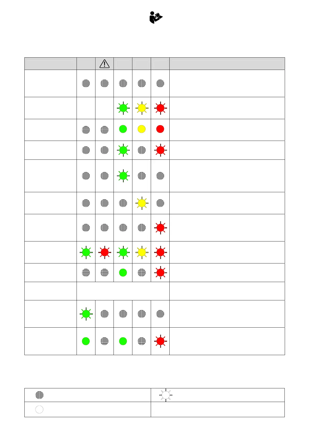
B.5 ALARM SIGNALS
Legend
ALARM DESCRIPTION
STAB
OK
PWR 90% 100% Problem Resolution
No power to system
- Check the fuse on the power supply cable
- Ensure the emergency stop buttons are not pressed
- Check for power on the supply cable
- Check for power on PIN1, connector X2
- Check for power on PIN 7C, connector X1
Pressure transducer
disconnected
- Check the pressure transducer
- Check the pressure transducer’s cable (X5-X1)
- Connect a 2Kohm resistor across connector X5 to simulate the
presence of the transducer
Pressure transducer input
short-circuited
1
2
3
- Check the pressure transducer
- Check the pressure transducer’s cable (X5-X1)
- Connect a 2Kohm resistor across connector X5 to simulate the
presence of the transducer
Electronic board not
programmed
- Recalibrate the moment limiter
Extension retract switch
open during system
startup
- Check switch “rientro estensioni FC” on the control valve
- Check the cable for switch “rientro estensioni FC” (X18-X4, X4-
X1)
- Check for voltage on PIN 1, connector X18
- Connect PIN1 to PIN2, connector X18, to simulate the
presence of the switch
Central switch open during
system startup
- Check the central switch on the control valve
- Check cables X12-X13-X14-X15-X16-X17 and XA-X1,
- Connect PIN1 to PIN2 on connectors X12, X13, X14, X15, X16,
X17
Stabilizer movement
switch open during system
startup
- Check switch “movimento stabilizzatori” on the control valve
- Check the cable to the stabilizer movement (X19-X4, X4-X1)
- Check for voltage on PIN1, connector X19
- Connect PIN1 to PIN2, connector X19, to simulate the
presence of the switch
All control valve
microswitches open during
system startup
- Check the condition of the switches on the control valve, and
the condition of their cables
- Connect PIN1 to PIN2 on connectors X12, X13, X14, X15, X16,
X17, X18,X19, X22, to simulate the presence of the switches
YVH1 powered (high)
contrary to control system
logic
- Check the condition of the cable connected to the emergency
valve
YVH1 in short circuit
No indication
Crane movements blocked
- Check the condition of the cable connected to the emergency
valve
Microswitch for 1st boom
lowering open during
system startup
- Check switch “1° braccio DOWN” on the control valve
- Check cable to switch “1° braccio DOWN”
- Check for presence of voltage on PIN1, connector X22
- Connect PIN1 to PIN2 on connector X22, to simulate the
presence of the switch
Signal to indicate closed
crane with load P1 >
P1max / 10 (approximate)
- Check the condition of the sensor for closed crane (the light on
the sensor should be off with crane open, on with crane
closed)
- Disconnect connector X6 to simulate crane open
- Check the condition of cable X6-X1
Light off
Light flashing
Light on
1... 2... 3
Sequence of illumination