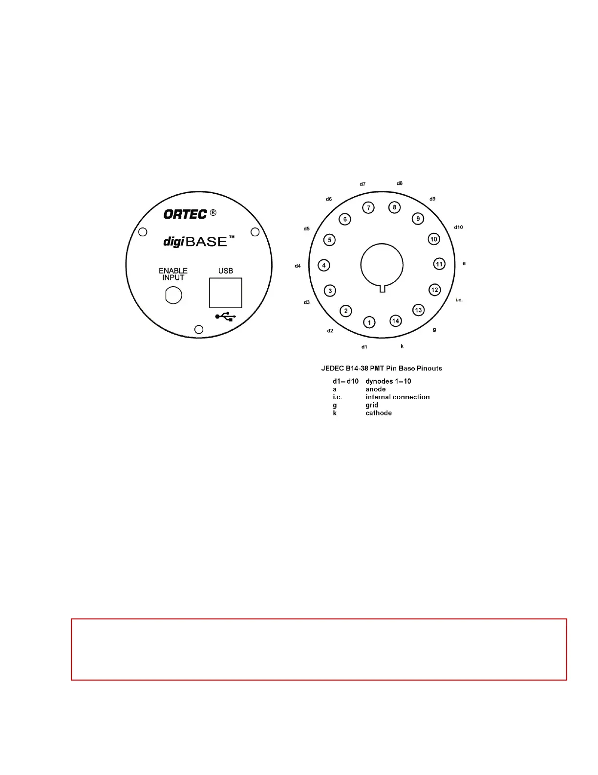
Figure 1. The digiBASE Connectors
2. GETTING STARTED
2.1. The digiBASE
Figure 1 shows the digiBASE connectors on both the top and bottom panels, including the pin
assignments for the TRW 3B14 socket base, which accepts JEDEC B14-38 PMT pin bases. The
digiBASE is powered by the USB bus so there is no separate power supply or cord. For more
information on the ENABLE INPUT and USB connector, see Chapter 3.
2.2. Setting the Coarse Gain Jumper
The digiBASE has 3 coarse gain settings, 1, 3, and 9, determined by setting a jumper within the
unit. The factory setting is 1×. (Fine gain is software-controlled within MAESTRO; see
Section 2.5.3.) To change the coarse gain:
! Disconnect the digiBASE from USB cable and wait 1 minute for the internal circuits to
completely discharge.
DANGER HIGH VOLTAGES are present on the tube socket and inside the unit.
Never operate the digiBASE with the shroud removed or without a detector
installed on the socket.
3

 Loading...