931003E / 0620 2. GETTING STARTED
Figure 10.
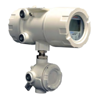
Mark Display
Selection
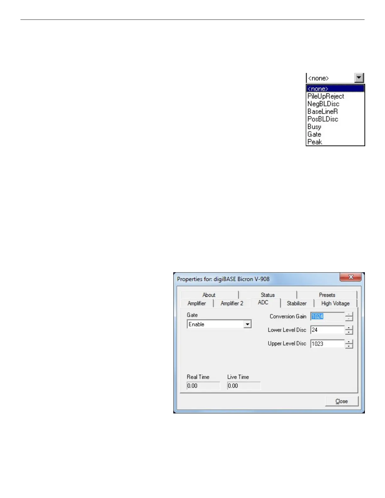
Figure 11. digiBASE ADC Tab
supports only PosBLDisc and Peak.
Mark Types
For the Mark, go to the Display/Preferences submenu and select
either Points or Fill All. This choice does not change the histogram
appearance in PHA mode.
None No channels are marked in the display.
PosBLDisc This shows when the positive baseline discriminator
has been triggered. The signal is used internally in
the live-time correction circuit.
Peak This is the peak detect pulse. It indicates when the
peak detect circuit has detected a valid pulse. The Mark
occurs about 0.5 ìs after the pulse maximum on the display.
On the lower right of the InSight display are the shaping parameter controls. Except for the LLD
control, accessed by clicking on the other controls... toggle, these are not functional for the
digiBASE.
2.5.3. ADC
This tab (Fig. 11) contains the Gate,
Lower Level Discriminator, and
Upper Level Discriminator controls.
In addition, the current real time and
live time are monitored at the bottom
of the dialog.
The Gate control allows you to
select a logic gating function. With
this function Off, no gating is per-
formed (that is, all detector signals
are processed).
When the Gate is set to Enable, if
the ENABLE INPUT is low (<0.8V),
real time, live time, and data acquisition are stopped. When the ENABLE INPUT is left open or
forced high (>2.0V), real time, live time, and data acquisition are enabled.
13

 Loading...