10
15120-101 Rev. D
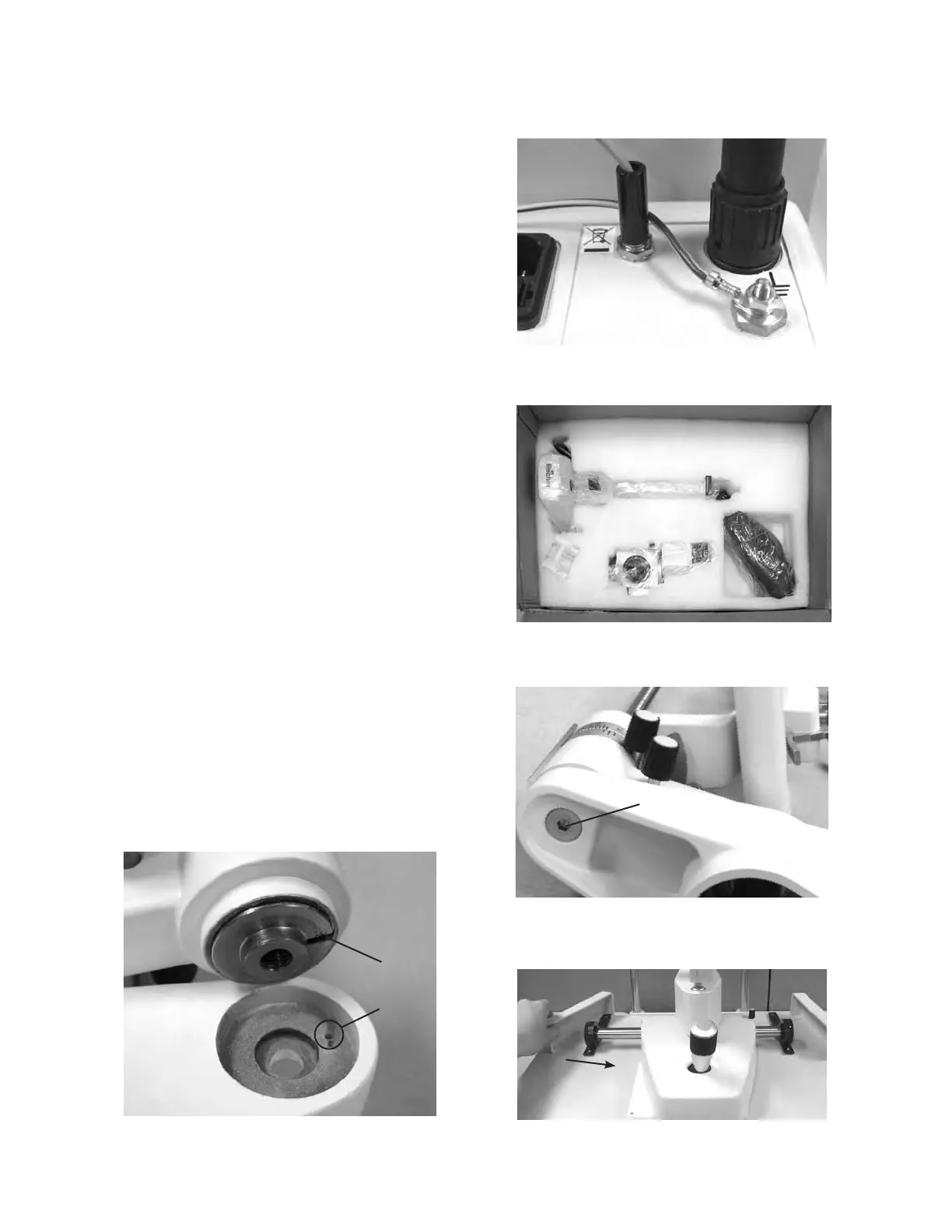
Unpacking and Installation (continued)
Attach the Fixation Light Wire from the Chin Rest 9.
Assembly into the connector on the back of the
Power Supply Assembly. Refer to Figure SU-6.
Open the box with the Microscope Assembly. 10.
Remove the Microscope Assembly, Base Assembly,
and Accessories. Refer to Figure SU-7.
Using the 5mm Hex Screw remove the Allen 11.
Screw on the bottom of the Illumination Assembly
and Arm.
Note: The Illumination Assembly and Arm are
connected as one piece.
Mount the Illumination Assembly and Arm onto the 12.
Base Assemnly and secure it with the Allen Screw
using the 5mm Hex Wrench. Refer to Figure SU-08.
Note: There is a Notch in the Base Assembly, and
a Slot in the Illumination Assembly. Align the
Illumination Assembly and Arm so the Notch
goes into the Slot. If the Notch is not aligned
properly,theSlitLampwillnotsitush,and
won’t be able to focus properly.
Refer to Figure SU-09.
Install the Base Assembly onto the tracks of the 13.
Table Top and slide the Guide Rail Covers around
the tracks. Refer to Figure SU-10.
Attach the Base Lamp Wire to the back of the 14.
Power Supply Assembly. Refer to Figure SU-6.
-continued-
Figure SU-9 Line Up Notch
Illumination
Assembly
and
Arm
Base
Slot
Notch
Figure SU-6 Connections
Chin Rest
Wire
Base
Lamp
Wire
Figure SU-7 Microscope, Base, Accessories
Base
Microscope
Accessories
Figure SU-8 Allen Screw
Allen
Screw
Base
Assembly
Arm
Illumination
Assembly
Figure SU-10 Base Install
Slide
Setup (continued)
 Loading...


