11
15120-101 Rev. D
Setup (continued)
Unpacking and Installation (continued)
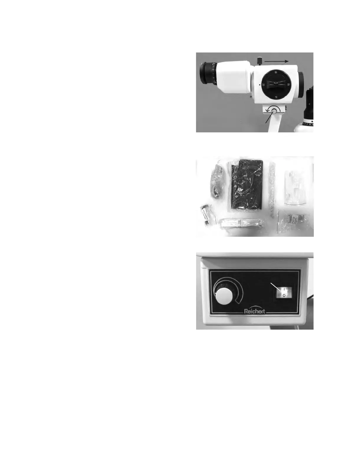
Install the Microscope Assembly onto the top of 15.
the Arm by sliding it into position, making sure
it is up against the stop. Then, tighten the Lock
Knob located on the right side of the Microscope
Assembly. Refer to Figure SU-11.
Note: Do not adjust the microscope stop knob
behind the base of the microscope or the
vertex distance will cause misalignment of
focus and require re-calibration of the slit lamp
assembly.
Remove the accessories and store them in an 16.
appropriate place so that when they are needed
they will be available. Refer to Figure SU-12.
Application of Input Power
WARNING: CARE MUST BE TAKEN TO ARRANGE THE
CABLES FOR THE ACCESSORIES SUCH THAT THEY DO
NOT PRESENT A TRIPPING HAZARD TO THE EXAMINER
OR A DANGER TO THE PATIENT.
WARNING: POSITION THIS INSTRUMENT SO THAT IT
IS NOT DIFFICULT TO OPERATE THE DISCONNECTION
DEVICE (PLUG).
After the unit is in its secure location, apply the 1.
correct input voltage to the instrument using the
Power Cord from the Accessory Tray.
Note: The power inlet is located on the backside of
the Power Supply Assembly.
Press down on the “|” located on the ON/OFF 2.
Switch. Refer to Figure SU-13.
Note: The ON/OFF Switch will illuminate green when
there is power to the unit. When the ON/OFF
Switch is set to off, the green light will turn off.
Disconnection of Input Power
At any time, the power switch can be set to OFF. 1.
The unit does not have a power down sequence.
To terminate operation of this instrument, press
the ON / OFF switch to the OFF position (O).
If this instrument is intended to be OFF for an 2.
extended period of time, it can be disconnected
from power by detaching the power cord from the
its receptacle.
Figure SU-11 Microscope Install
Turn Counterclockwise
Lock Knob
Microscope
Assembly
Slide
Figure SU-12 Accessories
Wrenches
Power
Cord
Guide Rails
Replacement
Bulb
Chin Paper
Dust
Cover
Focusing
Rod
Figure SU-13 Power Supply Assembly
ON/OFF Switch
 Loading...


