22
VXI-11 Discovery Protocol
The instrument has very limited support of VXI-11 which is sufficient for the discovery protocol
and no more.
The instrument implements a Sun RPC Port-mapper on TCP port 111 and UDP port 111 as
defined in RPC1183. The calls supported are: NULL, GET PORT and DUMP.
On TCP port 1024 a very simple VXI-11 protocol is implemented sufficient only for instrument
discovery. This implements the following calls: CREATE LINK, DEVICE_WRITE, DEVICE_READ
and DESTROY_LINK.
Once a link has been created anything written to the device is ignored and any read from the
device returns the identification string as would be expected from a “*IDN?” of the form
‘Manufacturer,Model,Serial No.,X.xx – Y.yy’
for example
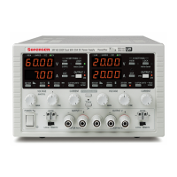
SORENSEN,XPF60-20DP,279730,1.00 – 1.00
where ‘X.xx’ is the revision of the main firmware and ‘Y.yy’ is the revision of the interface
firmware. Interface firmware is user field updateable via the USB port.
VISA Resource Name
Because of the limited support for VXI-11(Discovery Protocol only), the instrument must be
referred to by its raw socket information when used in software packages which communicate via
a VISA resource name. For example, an instrument at IP address 192.168.1.100 would normally
have a VISA resource name of "TCPIP0::192.168.1.100::inst0::INSTR" but for this instrument the
name must be modified to read "TCPIP0::192.168.1.100::9221::SOCKET" where 9221 is the TCP
port used by this instrument for control and monitoring, see below.
XML Identification Document URL
As required by the LXI Standard, the instrument provides an XML identification document that can
be queried via a GET at “http://<hostname>:80/lxi/identification” that conforms to the LXI XSD
Schema (available at http://www.lxistandard.org/InstrumentIdentification/1.0) and the W3C XML
Schema Standards ( http://www.w3.org/XML/Schema ). This document describes the instrument.
TCP Sockets
The instrument uses 2 sockets on TCP port 9221 for instrument control and monitoring. Text
commands are sent to this port as defined in ‘Remote Commands’ and any replies are returned
via the same port. Any string must be one or more complete commands. Commands may be
separated with either semicolons “;” or line feeds. No terminator is required since the TCP frame
contains complete commands though commands may be sent with a terminator if desired (it will
be ignored). Each command over TCP behaves as if it is terminated with a command terminator
(ASCII character 0AH, line feed).
LAN Error
If a LAN connection is made but an error is detected (e.g. the IP address is the same as another
device on the network) then the instrument’s LAN lamp (above the Output 2 meters) will be off
until the error is corrected. If a LAN error occurs; check and correct the configuration of the
instrument; a LAN Configuration Initialize (LCI) mechanism is provided via a recessed switch on
the rear panel ( marked LAN RESET) to reset the unit to the factory default. The default setting is
for the instrument to attempt to obtain settings via DHCP if available or, if DHCP times out (30
seconds), via Auto-IP. In the very unlikely event that an Auto-IP address cannot be found a static
IP address of 192.168.0.100 is assigned.
If no physical LAN connection is found at any time the LAN lamp will be off.

 Loading...


