TR-2100 User Manual 20
Power Supply Connection
The main power supply is connected to the terminal block at the lower left of the rear panel.
If a DC supply is being used, the polarity must be observed. The actual voltage specified
will be indicated in the System Drawings located in Appendix V of this manual. The
specified voltage must be used, and damage may occur if an incorrect voltage is applied.
The maximum wire size that the terminals will accept is 4 mm
2
(12 AWG).
There is one 6 mm earth stud at the rear of the TR-2100. The stud must be connected to a
main system earth with a suitable braided ground cable. This is required to ensure the safe
operation of the TR-2100.
Analogue & Digital Input Connections
The analogue input cables are connected to the orange strip connectors at the rear of the TR-
2100. The sequence of voltage and current transformer inputs must follow the User
Specification sheet. The maximum wire size for all analogue and digital inputs is 1.5 mm
2
(14 AWG). Smaller wire sizes can be accommodated using crimp terminations.
Voltage Inputs
The voltage inputs are connected directly to the standard 57 – 120V secondary windings of
protection or metering VTs. The actual nominal and full-scale voltages are given in the
System Drawings in Appendix V.
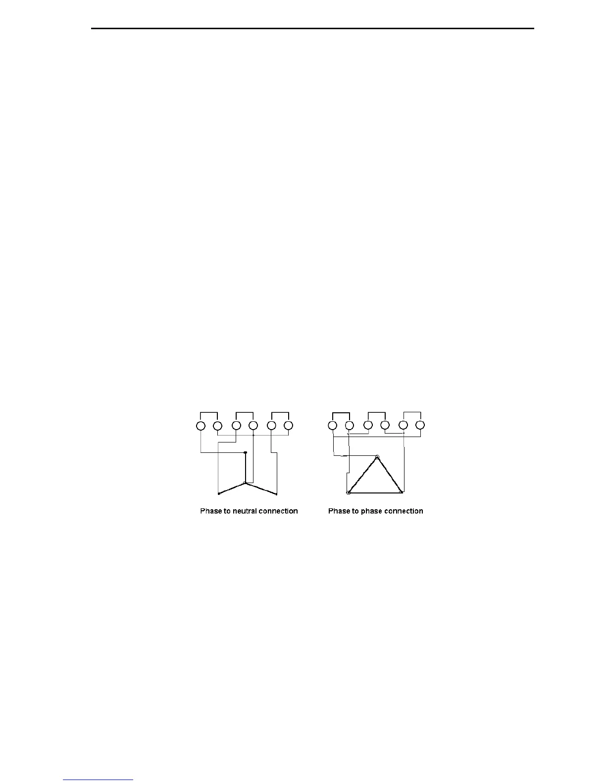
Figure 5 VT Wiring Options
Since all inputs are isolated from each other, either phase-to-phase or phase-to- neutral
windings can be connected.
 Loading...