TR-2100 User Manual 23
Auxiliary Connections
Serial and Parallel Ports
If an external modem or local printer has been specified, they are connected to the 9-pin D
and 25-pin D connectors at the right of the rear panel. The RS232 connectors may also be
used for direct connection of a computer for Display Station communications (Display
Station communications require hardware handshaking signals RTS & CTS).
The connectors conform to the IBM PC format for RS232 serial and Centronics parallel
ports, respectively. There is also a front mounted 9-pin RS232 port available for serial
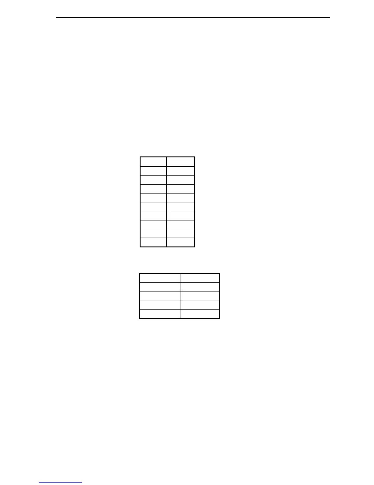
connections. Both the front and rear RS232 communications ports have the following pin
configurations:
Pin Use
1 DCD
2 Rx
3 Tx
4 DTR
5 Gnd
6 DSR
7 RTS
8 CTS
9 RI
The data format is:
Baud rate 19200*
Parity None
Data bits 8
Stop bits 1
Handshake Hardware
* The actual baud rate is settable within Display Station
Serial Time Code Port
When a number of recorders are used at a single site, a single GPS receiver can be used to
provide extremely accurate time synchronization between units. This requires connection of
an external satellite antenna to one TR-2100 chassis, which we will call the “master”
recorder. For time locking multiple recorders together, both the fiber optic and RS485 serial
ports must be daisy chained between units.
Optical 1 PPS port
An accurate 1 pulse per second (1 PPS) signal is provided on the optical port at the rear of
the TR-2100. The 1 PPS output from the master recorder is connected to all the others via
low cost fiber optic cable to provide the time reference. A second port is also provided to
allow daisy chaining several units.
 Loading...