TR-2100 User Manual 24
To distribute the one second pulse, the optical cables are ‘daisy chained’ together. The 1
PPS optical Output from the master recorder (with the GPS receiver) is connected to the
next recorder’s Input. Its Output is connected to the next Input and so on. Any number of
recorders can be linked in this manner.
RS485 Connection
The RS485 time code output can be daisy-chained directly from the master to drive up to 30
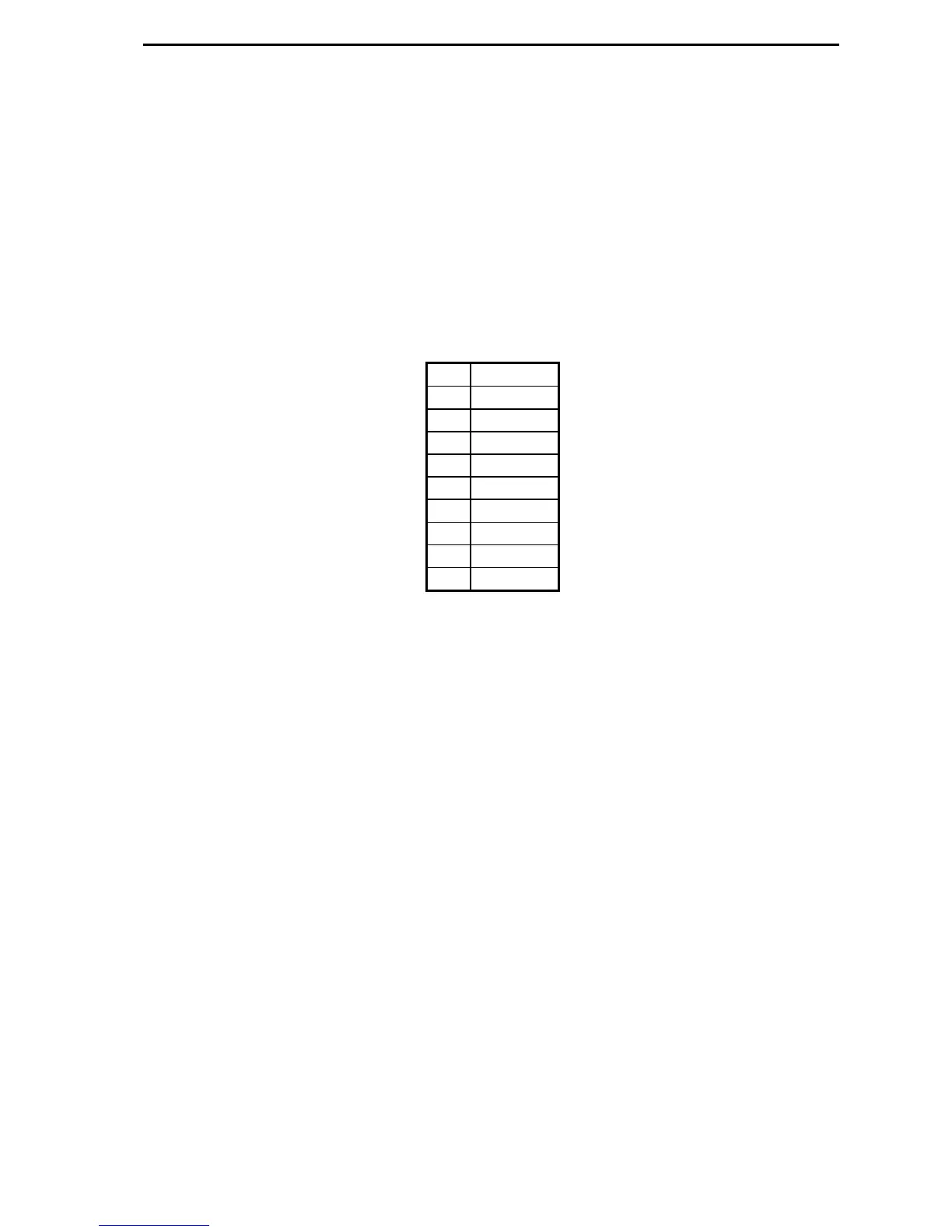
recorder “remotes” time code inputs. The polarity of the connections must be observed. The
RS485 9-pin D connections are:
Pin Function
1 Input +
2
3
4
5 Output +
6 Input -
7
8
9 Output -
Connect the Output + and – pins on the master to Input + and – pins (respectively) on each
remote.
A 120-ohm, ¼ W termination resistor must be installed at the beginning and end of the
RS485 string. Insert the resistor in the cable connector across pins 5 and 9 at the master unit.
Insert another resistor across pins 1 and 6 at the very last remote unit of the RS485 string.
All units in-between do not require termination resistors.
 Loading...