Versitron Operation Manual 11
4.0 INSTALLATION AND SETUP
4.1 Test Stand Installation
The Versitron machines are heavy machines and great care should be taken in
choosing the location where is to be installed. Ensure the bench is capable of
remaining firm and stable withstanding the combined weight of the machine and any
accessories supplied. Please see the Specifications page (section 7.0) for the weight
of the apparatus.
Suitable lifting equipment should be used when lifting the Versitron machine; i.e. a
hydraulic floor hoist (2t capacity, recommended) and a polyester sling (5t. rating,
recommended). Please ensure outmost care is taken when lifting this instrument, use
safe working practices.
The tester is shipped in two crates, one containing the Stand with an Accessory Kit
and one containing the Test Head.
Included in the Accessory Kit should be:
• Set of Allen wrenches
• 2” Vee anvil
• Spot anvil
• Test blocks
• Wrench to remove elevating unit
• Pin wrench
• Small Vee anvil
• 1/16” ball indenter
• Anvil base collet
• Calibration block
• Vinyl protective cover
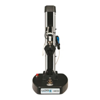
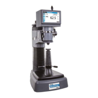
Lifting the Versitron machine
(AT130N shown)
Ensure the sling is
wrapped around this
area of the machine
(as shown).
 Loading...