STEPS
Part II: Electrical Connections for the Analyzer
• Verify your rated power supply matches the operating voltage of your Analyzer before
you begin
• THE MODEL 210BX is available with either AC or DC Power (you must request your
desired power at the time of your purchase)
Note: Refer to page 50 for the power requirements of your Analyzer.
Note: Both alarm relays are rated for 5A @115VAC or 24VDC.
• Your Analyzer has both 1–5 VDC and 4–20mA isolated analog signals. It has been
setup at the factory per your analog output requirements at the time of purchase.
However, this can be easily changed in the field by following the instructions shown on
page 33
• Flameproof joints are not intended to be repaired
• Electrical bushing separating the Flameproof and Analytical enclosures shall not be
subject to environmental conditions which adversely affect the properties of the cement
Key Points:
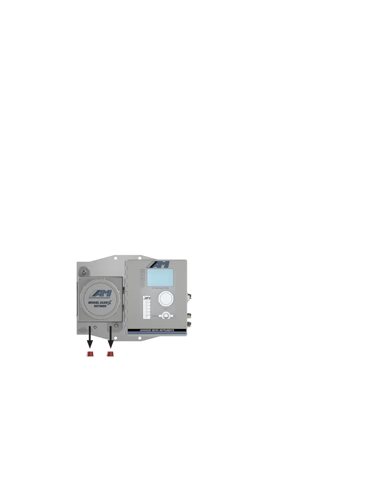
1. Remove the two red plastic protective caps from the ½" NPT conduit holes on the explosion-proof
side of the Analyzer. These plastic caps protect the threads of the unit during shipping.
• We provide 2 (two) separate ½" NPT conduit holes to accommodate all electrical connections.
The first conduit opening should be used for power and alarm relay connections. The second is for
analog output and RS485 connections
Note: AC Power and the opening and closing of alarm relays produce both electrical noise and
large inductive spikes that can have an undesirable effect on the measurement readings. This is why
we provide two conduit openings and strongly recommend separating the sensitive analog signal
wiring from the power and relay wiring.
9