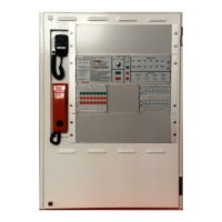
EV3000
COMMISSIONING LOG BOOK
5 Completing the Commissioning Report
To complete the commissioning report, Appendix A, follow the procedure below and use the sample
(Appendix B) as a guide.
1. List the EWS zone number.
2. List the amplifier wattage and confirm with the quotation request that it is correct.
3. Calculate the speaker load for each EWS zone.
Formula: No. of Ceiling Speakers x tapping = W
And No. of Horn Speakers x tapping = W
TOTAL SPEAKER LOAD = W
Example: 9 Ceiling speakers x 2 watt tapping = 18 W
And 2 Horn speakers x 2.5 watt tapping = 5 W
TOTAL SPEAKER LOAD = 23 W
4. Confirm the speaker quantity and load with the quotation request.
5. Ensure that the amplifier wattage is sufficient to drive the speakers.
6. Ensure that all loud speakers are of the required specification and are approved by the
EWIS Manufacturer.
7. Ensure that all loud speakers are suitable for their environment.
8. Open circuit the wiring at one loud speaker in each zone to ensure a fault is displayed on the
EWS zone control panel at the MECP.
9. Repeat test with short circuit.
10. Check that the back ground music is correct, if zoned; confirm that the installation is as per
the quotation.
11. Measure the sound level for public address, alert and evacuation tones. Ref AS 2220-2
Clause 2.2.3.
12. Ensure tones are of correct type, i.e. either AS2220 or ISO 7731 / 8201.
13. At the Fire Indicator panel list the zone numbers that correspond to the EWS zones.
14. Open circuit each FIP circuit and ensure a fault is displayed on the EWS zone control panel
at the MECP.
15. Simulate an alarm at the FIP and ensure that the correct evacuation zone responds. Repeat
for all Fire Alarm inputs.
16. Open circuit the wiring at each WIP to ensure a fault is displayed on the EIS zone control
and the EWS zone control panel at the MECP.
17. Short circuit the wiring at each WIP to ensure fault is displayed on the EIS zone control and
an alarm is initiated on the EWS zone control panel at the MECP.
18. Check the operation of each WIP as per the instructions in the EV3000 Operators Manual.
Ref AS 2220-1 Section 3.
19. Note the EIS zone numbers of WIP's in each EWS zone.
20. Check each EAID has a 10K ohm EOL resistor installed, Open circuit the wiring and ensure
a fault is displayed on the EWS zone control panel at the MECP.
21. Short circuit the wiring at each EAID and ensure that it initiates the correct evacuation
sequence.
22. Note the number of EAID's per EWS zone.
23. Open circuit the wiring at one pair of visual alarms in each zone to ensure a fault is
displayed on the EWS zone control panel at the MECP. Repeat test with short circuit
24. Operate both alert and evacuate visual alarms, note the results. Ref AS 2220-2 Clause
2.2.4.

 Loading...