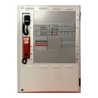
EV3000
COMMISSIONING LOG BOOK
3 Wiring
Check that the installation requirements of AS 2220.2 – Section 5 are complied with
NOTE: Complete the following tests with all power turned off / disconnected.
3.1 Mains Connection
Check that the AC Mains Power supply is installed in accordance with AS2220.2 - 1989 Section 4.
3.2 Speaker Connection
Test the speaker wiring at the MECP to ensure that the circuit is correct.
Method: with the power turned off place an ohmmeter across the first speaker circuit for
approximately five seconds. The end of line resistance of 47kΩ should be present.
Record the result on the Commissioning Record by ticking the appropriate box.
Repeat for each circuit.
3.3 Warden Intercom Point Connection
Test the WIP wiring at the MECP with the line disconnected from the 302-6270 to ensure that the
circuit is correct.
Method:
2 WIRE WIP: With the power turned off and the WIP handset hung up, place an ohmmeter across
the lines denoted ‘W’ and ‘C’. A resistance of 22K should be present.
3 WIRE WIP: With the power turned off and the WIP handset hung up, place an ohmmeter across
the lines denoted ‘W’ and ‘C’. A resistance of between 90kΩ and 110kΩ should be present.
Record the result on the Commissioning Record by ticking the appropriate box.
Repeat for each circuit.
3.4 Warden Intercom Point with EAID connected
Test the WIP wiring as in section 3.3.
Method:
2 WIRE WIP: With the power turned off and the WIP handset hung up, place an ohmmeter across
the lines denoted ‘W’ and ‘C’. A resistance of 6.8K should be present.
3 WIRE WIP: Measure the resistance from the third wire ‘E’ to either of the WIP lines. The resistance
should be between 1MΩ and 3MΩ dependent on the type of meter used.
Record the result on the Commissioning Record by ticking the appropriate box.
Repeat for each circuit.
3.5 Visual Alarm Connected
Test the visual alarm wiring at the MECP to ensure that the circuit is correct.
Method: with the power turned off place an ohmmeter across the first circuit for approximately five
seconds. A resistance between 100kΩ and 4MΩ should be present (actual value will vary with visual
type and meter type).
Record the result on Commissioning Record by ticking the appropriate box.
Repeat for each circuit.
3.6 Fire Alarm Inputs
Test the FIP input wiring at the MECP to ensure that the circuit is correct.
Method: with the power off place an ohmmeter across the common and each input. An end of line
resistance of 10kΩ should be present.

 Loading...