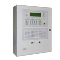
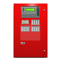
FIREFINDER SERIES II INSTALLATION, COMMISSIONING &
OPERATION
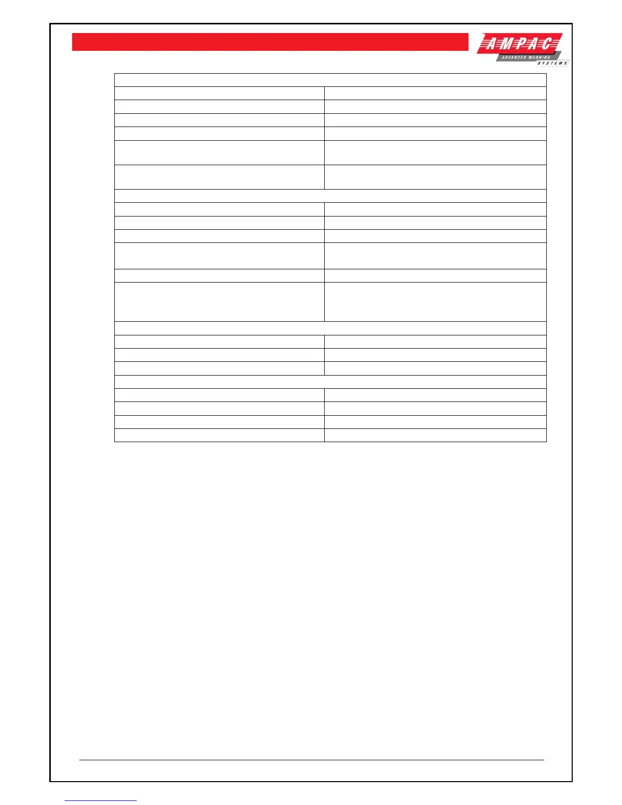
4.6 Operational Parameters
Max No of Devices per Loop
Max No of Devices per FACP
Max No of Devices per Conventional Zone
Cable Loop Characteristics
2 core. 1.5 to 2.5mm² Max loop resistance 50Ω.
Max core to core capacitance 0.5uF
Max/Min conductors sizes terminals can
accept
Power Supply Output Voltage
Power Supply Output Current
240 mA (min 1 loop fitted)
310 mA (min 4 loops fitted)
Minimum Operating Voltage
Battery Type & Capacity
Note: A greater range of batteries can be
supplied if using a remote battery cabinet
2 x 12V sealed lead-acid
CP10-1 = 12AH
CP10-4 = 24AH
500mm (H) x 405mm (W) x 140mm (D)
840mm (H) x 515mm (W) x 140mm (D)
Note: Except for the batteries component life expectancy is in the order of 15 years. Battery life
will depend on the environment and the quality of the battery.
Note: Short Circuit Isolation should be provided on the analogue loop in appropriate places so
that a short circuit on the loop does not prevent more than 32 fire detectors from indicating an alarm.
Note: A separate cabinet for the batteries is available should the FACP be optioned to
capacity.
 Loading...