6 Expanding the System Through Networking
Expanding the system can be achieved in various ways and requires the use of boards specifically
designed for communications purposes and boards that actually expand the system.
6.1 Communications: Network Interface Card
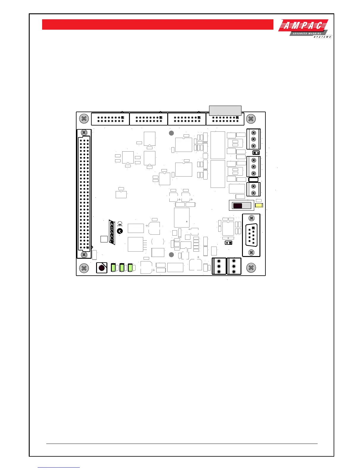
The Network Interface Board provides the RS485 communication buses via CN18 on the Main
Controller (Loop Comms) to allow the networking of multiple panels in different combinations, e.g.
from Data Gathering Panels (DGP) to Peer to Peer panels. Fitted to the NIC is the CPU IO Controller
with NIC software to control the in out flow of communications.
Figure 53: Network Interface Board Layout
When FACP’s are connected to each other they form a “NETWORK“. Individual FACP’s in the
Network are referred to as NODES. The Network as defined by the limitations of the installation can
consist of a number of Nodes, the number of Nodes being dependant on the configuration of each
Node. Typically an entire Network could consist of 60 Slave CPU’s connected to loops, zones and or
input / output devices spread over several nodes. The Network is Peer to Peer with the entire system
configuration being stored at each Node. The system is then programmed so that information can be
made invisible to particular Nodes or visible to all Nodes. Likewise system commands can be global
or restricted to specific parts of the network.
The entire system can be programmed from Node 1 in the Network and is connected as a data loop
which provides redundancy should there be a single cabling fault.
IMPORTANT
While it is important that proper documentation is kept and maintained for any installation it becomes
even more important as a system develops into the larger types described above.
 Loading...