Installation
7
MXA-MP/MPL Modero X Series® Multi Preview and Multi-Preview Live
Installation
Overview
Both the MXA-MP and MXA-MPL may be installed in a freestanding location, such as on a desktop or table,
but both devices may also be installed in a standard AV rack. This should be done to ensure accessibility to the
Modero X Series touch panel receiving the device’s video or image output.
Installing the MXA-MP and MXA-MPL
In a network, the MXA-MPL or MXA-MPL must be connected between the Enova DVX or DGX and the
Modero X Series touch panel (FIG. 3). Multiple devices may be used for touch panels on a network, but each
individual device cannot be used by multiple Modero X Series touch panels.
When using the MXA-MP or MXA-MPL with a Modero X Series touch panel, the device may be used to
supply power to the touch panel in certain circumstances. (For more information, please refer to the Maximum
Power Cable Gauges and Distances section on page 9.) Instead of using a separate external power source,
touch panels using an external power source may also connect to the device via the 2-pin connector output on
the device’s back (FIG. 4).
NOTE: For full functionality, the MXA-MP and MXA-MPL should be used with the
Enova series media switchers and Modero X Series touch panels. Neither device
may be used with previously released AMX touch panels or media switchers.
FIG. 3 MXA-MP/MPL Installation Diagram
AMX-certified
PoE injector
(if needed)
MXA-MP/MPL
Modero X Touch Panel
1
Enova DVX or DGX
2
3
4
5
6
7
8
9
10
Source
Devices
HDMI
CAT 5
LAN/WAN
MXA-MP/MPL Installation Diagram
LAN
When connecting an Enova DVX to an MXA-MP or MXA-MPL, an HDMI cable
adaptor may be necessary to make the connection from the DVX’s HDMI cable to the
MXA-MP/L’s Video Input port.
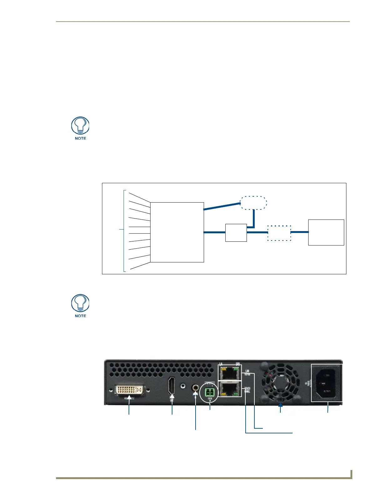
FIG. 4 Rear of the MXA-MP/MPL, showing input and output power
Video
Input
HDMI
Out
Audio In
2-pin
Connector
Output
Ethernet In
Ethernet
Out (to
Touch Panel)
Ventilation
Fan
Power
Input
Rear