Wiring and Installation
8
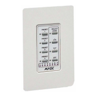
PRO-DP8 Decor 8-Button Wall Panel
3. Change DIP switches 4 and 5 to match those values listed in the following table for the number
of desired Packs (1-3).
4. Reconnect the PROlink cable to the PROlink bus connector located at the rear of the
PRO-DP8.
Wiring the PRO-DP8
The PRO-DP8 uses a 4-pin PROlink connector for power and data, located on the back of the panel.
PROlink wiring guidelines
! Use 24-gauge twisted-pair cable for runs of 300 feet (91.44 meters) and under.
! Use 22-gauge shielded low-capacitance cable for runs of up to 1,000 feet (304.8 meters).
! Additional panels can be daisy-chained or connected directly to the Pack's terminal.
! Avoid connecting more than three PRO-D:P:S to a Pack without a separate power supply
for the panels (see the Using a PROlink 4-pin connector with an external 12 VDC power
supply section on page 9 for details).
Preparing captive wires
You will need a wire stripper, and flat-blade screwdriver to prepare and connect the captive wires.
1. Strip 0.25 inch (6.35 mm) of wire insulation off all wires.
2. Insert each wire into the appropriate opening on the connector according to the wiring
diagrams and connector types described in this section.
3. Turn the flat-head screws clockwise to secure the wires in the connector. Do not over-torque
the screws; doing so can bend the seating pins and damage the connector.
Using a PROlink 4-pin connector for data and power
These steps describe how to connect the dimmer Pack's PROlink connector to the PROlink
connector (male) on the rear panel of the PRO-DP8 for data and 12 VDC power.
1. The captive-wire terminal on the PRO-DP8 is wired to an orange captive-wire terminal on the
Pack. Insert each wire into the appropriate opening on the connector, according to the wiring
diagram shown in FIG. 1.
DIP Switch Settings for 1, 2 or 3 Packs
DIP Switch 4 DIP Switch 5 Pack 1-3 Result
OFF OFF Pack 1 ONLY Channels 1-6 (Pack 1)
ON OFF Packs 1 & 2 Channels 1-12 (Packs 1 and 2)
OFF ON Pack 2 ONLY Channels 7-12 (Pack 2)
ON ON Packs 2 & 3 Channels 7-18 (Packs 2 and 3)
Check for short circuits and continuity before connecting panels to the PROlink
connector on the dimmer Pack.