AD9959/PCB
Rev. 0 | Page 18 of 28
Single Tone Mode
Open the Single Tone Mode folder to access the single tone mode of operation example setup files. This section discusses the
All Channels on @ 10_20_30_40MHz_RURD enabled.stp file.
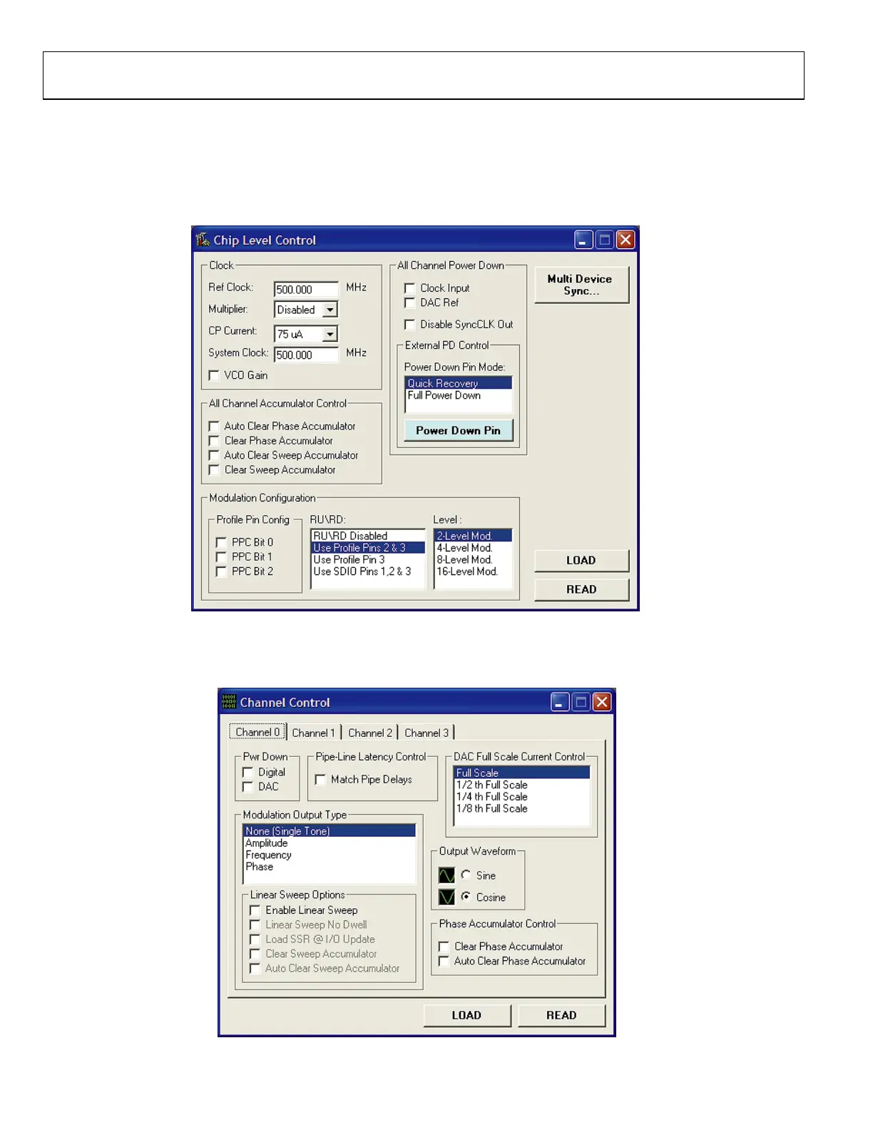
The Chip Level Control window (Figure 37) from this particular setup shows that a 500 MHz System Clock is running, with the RU/RD
operation enabled. In the RU/RD box, Use Profile Pins 2 & 3 has been selected to control the RU/RD feature.
05698-037
Figure 37.
In the Channel Control window (Figure 38), each channel has None (Single Tone) selected for their modulation output as shown in the
Modulation Output Type box.
05698-038
Figure 38.

 Loading...


