AD9959/PCB
Rev. 0 | Page 6 of 28
Windows XP Users
1. Power up the AD9959 evaluation board (see Table 2).
2. Connect the evaluation board to the computer using a USB
cable via the USB port. Then, the VBUS LED (CR1 on
AD9959 evaluation board) illuminates.
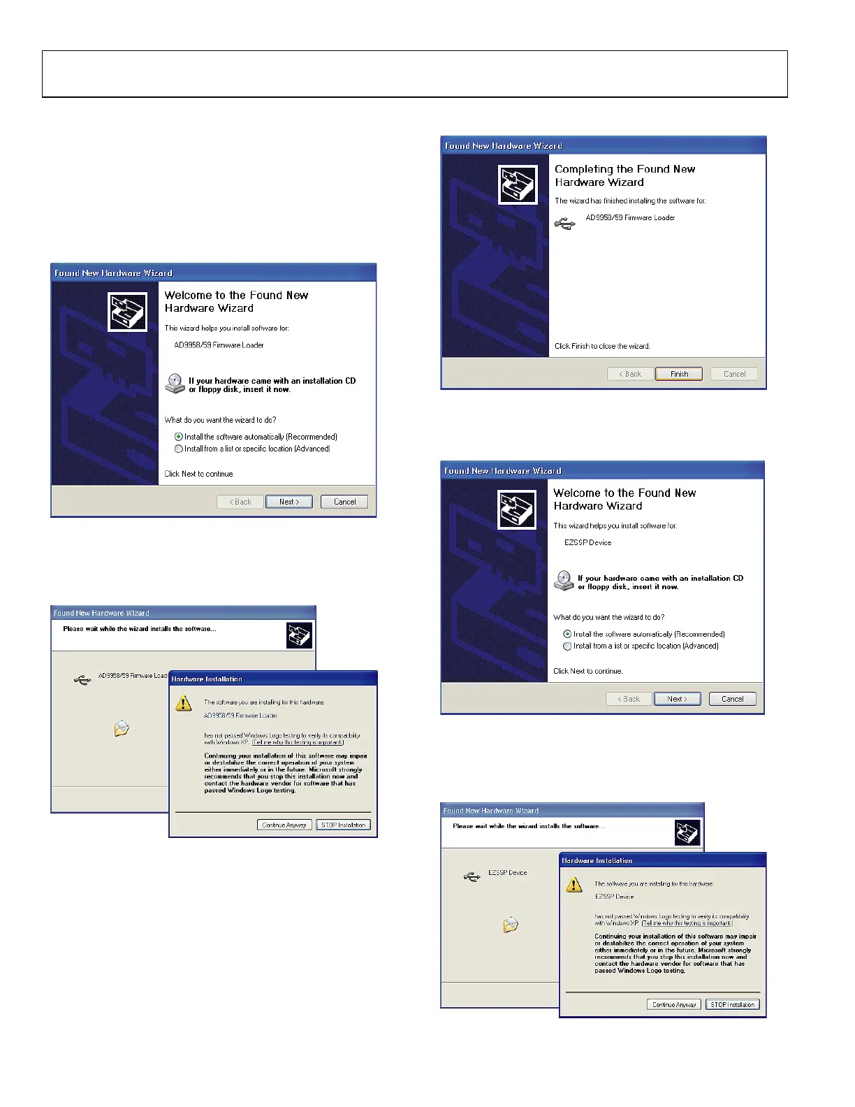
3. When the USB cable is connected, the screen below
appears (Figure 7). Click Next to continue.
05698-007
Figure 7.
4. Click Continue Anyway when you see the window in
Figure 8.
05698-008
Figure 8.
5. Click Finish after this window (Figure 9) appears.
05698-009
Figure 9.
6. Click Next after you see the window below (Figure 10).
05698-010
Figure 10.
7. Click Continue Anyway when this window
(Figure 11) appears.
05698-011
Figure 11.

 Loading...


