AD9959/PCB
Rev. 0 | Page 22 of 28
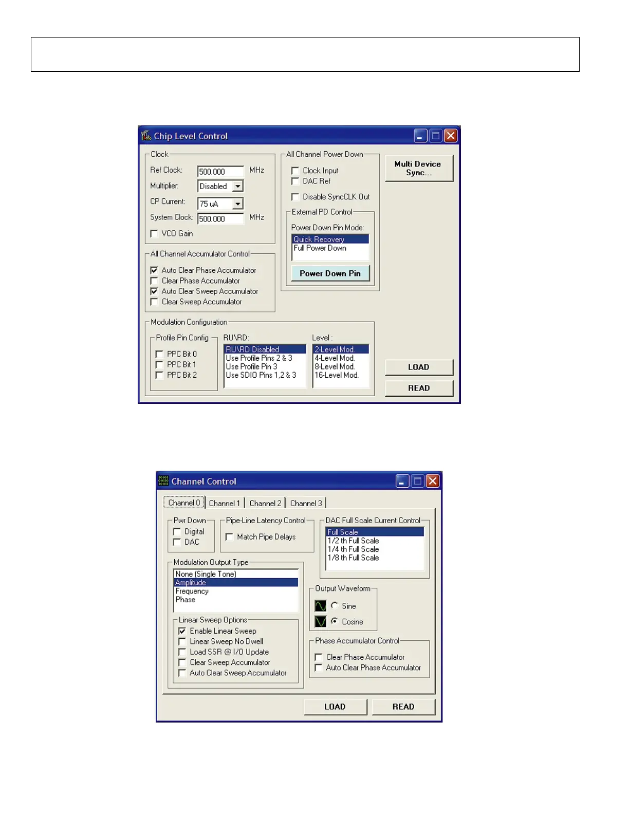
The Chip Level Control window (Figure 45) from this particular setup shows that a 500 MHz System Clock is running with RU/RD
disabled. The Auto Clear Phase Accumulator and Auto Clear Sweep Accumulator boxes have been checked in the All Channel
Accumulator Control section to ensure synchronization across channels and reinitialize the starting point once the linear sweep ends.
05698-045
Figure 45.
In the Channel Control window (Figure 46), each channel has Amplitude selected for its modulation output as shown in the
Modulation Output Type box. As discussed earlier in the Linear Sweep Options section, the Enable Linear Sweep box found in Linear
Sweep Options section must be checked in order to configure the part for the linear sweep mode of operation.
05698-046
Figure 46.

 Loading...


